System for regulating speed of an internal combustion engine

a technology of internal combustion engine and speed regulation, which is applied in the direction of electric generator control, electric control, speed sensing governor, etc., can solve the problems of inacceptable speed variations for certain applications, and achieve the effect of improving speed regulation

Inactive Publication Date: 2005-04-05
CUMMINS INC
View PDF37 Cites 64 Cited by
  • Summary
  • Abstract
  • Description
  • Claims
  • Application Information

AI Technical Summary

Benefits of technology

One form of the present invention is a unique internal combustion engine system. Another form of the present invention includes a unique technique for adjusting air / fuel ratio (lambda) to regulate engine speed. These and other forms may also include active spark timing, throttle control, and / or transient air mass flow estimation to further improve speed regulation.

Problems solved by technology

However, such systems still allow engine speed variations that may be unacceptable for certain applications.

Method used


Image

  • System for regulating speed of an internal combustion engine
  • System for regulating speed of an internal combustion engine
  • System for regulating speed of an internal combustion engine

Examples


Embodiment Construction

For the purposes of promoting an understanding of the principles of the invention, reference will now be made to the form illustrated in the drawings and specific language will be used to describe the same. It will nevertheless be understood that no limitation of the scope of the invention is thereby intended. Any alterations and further modifications in the described or illustrated embodiments, or further applications of the principles of the inventions contained herein are contemplated as would normally occur to one skilled in the art to which the invention relates.

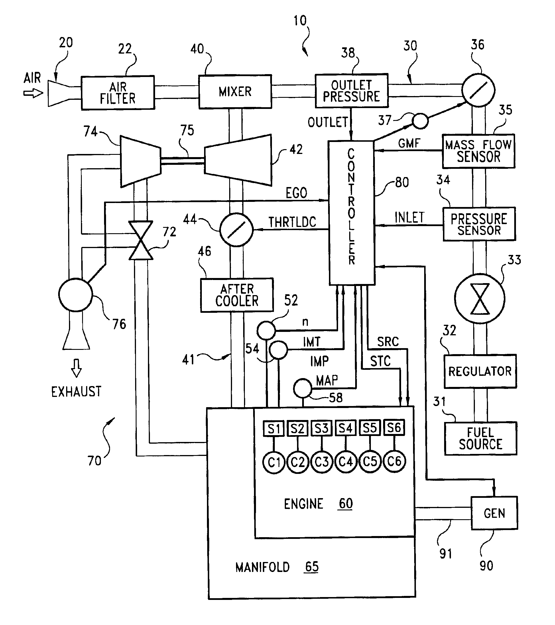
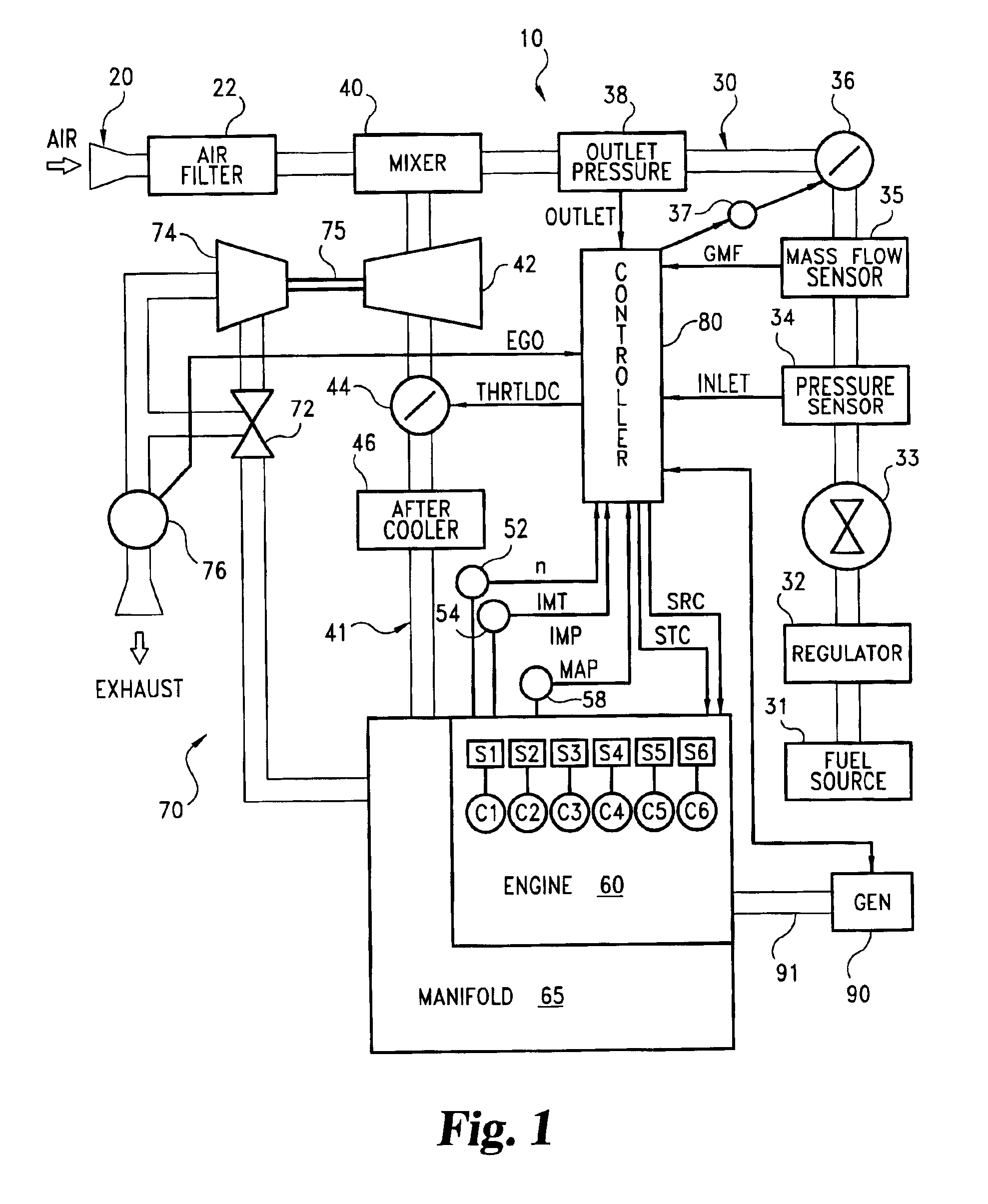
FIG. 1 illustrates an electrical generation system 10 of one form of the present invention. System 10 includes engine 60 operable to drive electric power generator 90 through mechanical linkage 91. Linkage 91 can include one or more drive shafts, gears, clutches, drive chains or belts, and the like suitable to provide mechanical power to generator 90 with engine 60. Controller 80 of system 10 is operatively coupled to v...


PUM


Abstract

An internal combustion engine system is disclosed that improves regulation of engine speed relative to a speed setpoint. The system controls ignition timing, throttle plate actuation, fuel valve actuation or a combination thereof in accordance with maintaining a setpoint speed. The system also includes a transient air flow estimation for further improving setpoint speed accuracy.

Description

BACKGROUNDThe present invention relates to internal combustion engines, and more particularly, but not exclusively, is directed to operating techniques for a turbocharged internal combustion engine driving an electrical power generator.In certain applications it is generally desirable to control rotational speed of an internal combustion engine. This is particularly true in applications where the engine is a prime mover for an electrical power generator. Often, proper performance of electrical equipment being powered by such a generator requires that alternating current (AC) be provided at a generally constant frequency, despite changes in generator load, operating conditions of the engine, etc.Previous attempts have typically utilized one particular engine control subsystem, such as throttle control, to maintain engine speed at a desired speed setpoint, while simultaneous utilizing other control subsystems to optimize different parameters. However, such systems still allow engine s...

Claims


Application Information

Patent Timeline
Patent Type & Authority Patents(United States)
IPC IPC(8): F02D37/00F02D41/00F02D37/02F02D31/00F02P9/00F02D29/06F02D41/14F02D11/10
CPCF02D31/001F02D37/02F02D41/0005F02D41/0007F02P9/005F02D11/105F02D2041/1419F02D41/1456F02D41/187F02D2041/1409F02D2200/0406F02D2200/0414F02D2200/0602F02D2200/0614Y02T10/144Y02T10/42F02D29/06Y02T10/12Y02T10/40
Inventor THOMAS, ROBERT J.VANDENBERGHE, TERRY MCARROLL, MATTHEW S.
Owner CUMMINS INC
Why Eureka
Try Eureka