Damped longitudinal mode latching relay

a relay and longitudinal mode technology, applied in relays, generators/motors, contacts, etc., can solve the problems of solid contact relays, contact damage, and degraded conductivity, and achieve the effect of preventing damag

Inactive Publication Date: 2005-04-05
AGILENT TECH INC
View PDF24 Cites 10 Cited by
  • Summary
  • Abstract
  • Description
  • Claims
  • Application Information

AI Technical Summary

Benefits of technology

The present invention relates to an electrical switch in which a solid slug is moved within a channel to make or break an electrical circuit between contact pads in the channel. The solid slug is moved by piezoelectric elements. In an exemplary em

Problems solved by technology

Rapid switching of high currents is used in a large variety of devices, but provides a problem for solid-contact based relays because of arcing when current flow is disrupted.
The arcing causes damage to the contacts and degrades their conductivity due to pitting of the electrode surfaces.
However, the use of heated gas

Method used


Image

  • Damped longitudinal mode latching relay
  • Damped longitudinal mode latching relay
  • Damped longitudinal mode latching relay

Examples


first embodiment

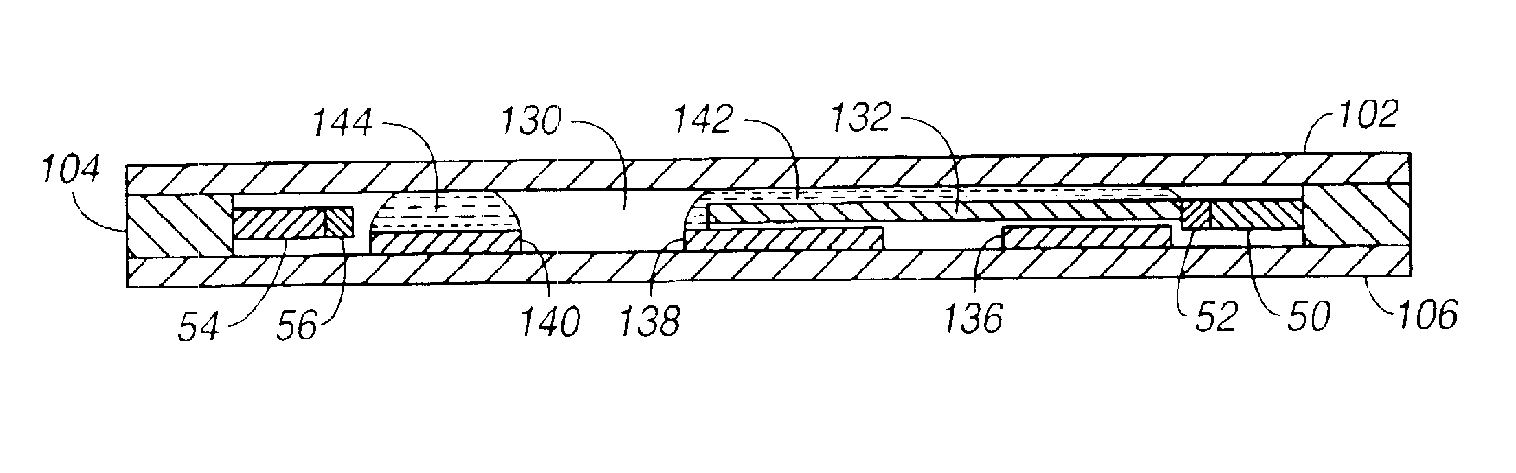
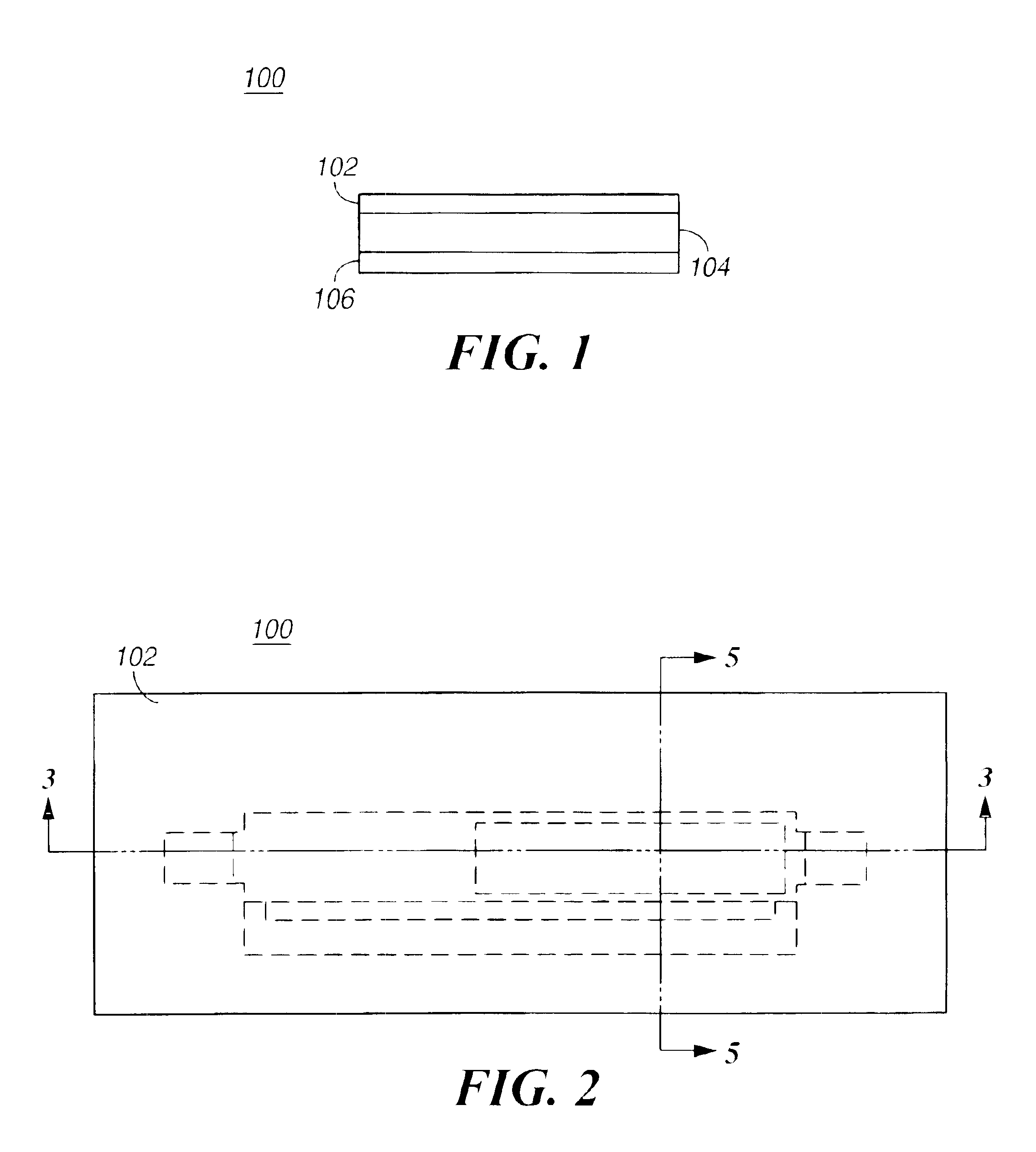
In order to prevent the brittle piezoelectric elements from breaking when the switching slug arrives at its new locations during switching, energy dissipative elements are used to lessen the impact forces. In the invention, shown in FIG. 3 and FIG. 4, compliant, energy absorptive faces 52 and 56 are used on the piezoelectric elements 50 and 54, respectively. Materials such as “Sorbothane” are effective at absorbing shock and vibration. An alternative embodiment is described below with reference to FIG. 6.

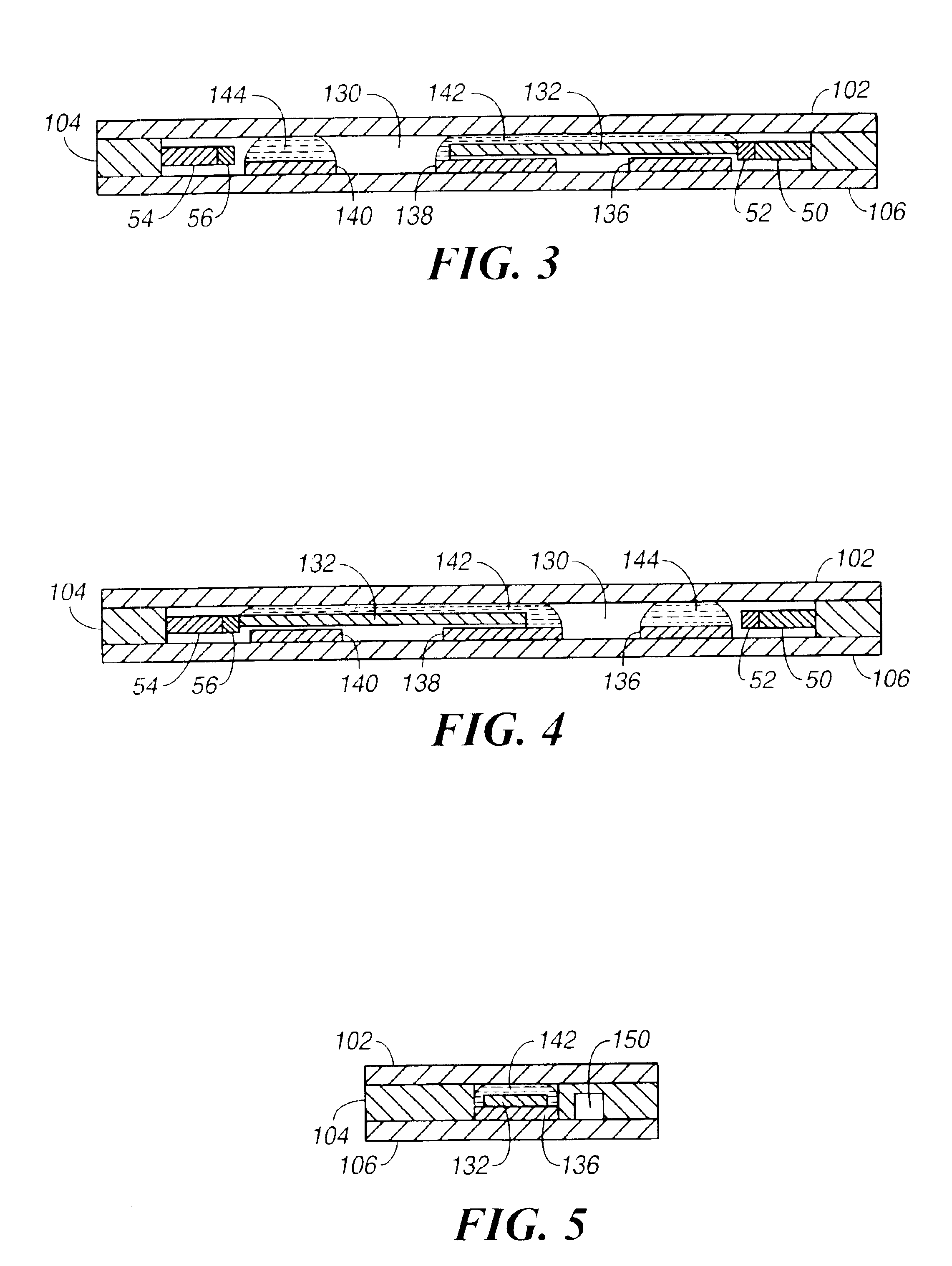
FIG. 5 is a sectional view of the relay through the section 5—5 shown in FIG. 2. The solid slug 132 rests on the contact pad 136 and is held in position by surface tension of the conducting liquid 142. A pressure relief passage 150 is coupled to the ends of the switching channel and allows fluid to flow from one end of the switching channel to the other.

second embodiment

FIG. 6 is a top view of the switching layer 104 of the relay. A pressure relief channel 150 is coupled to the ends of the switching channel 130 by vent holes 152 and 154. The pressure relief channel 150 allows pressure variations in the switching channel, due to movement of the solid slug 132, to be equalized by allowing fluid to flow from one end of the switching channel to the other through the vent holes. When the actuator 50 pushes the slug 132 to actuate it, the actuator face pushes the slug to the level of the vent opening 152, relieving any vacuum between the actuator face and the end of the slug that would tend to hold the slug back. The slug preferably has shaped ends that are just wide enough to fit into the recesses in which actuators 50&54 reside. In the embodiment shown in FIG. 6, the energy absorptive faces 52 and 56 are absent and the switching channel is narrowed near the piezoelectric actuators so there is little clearance between the channel walls and the portion o...


PUM


Abstract

A piezoelectric relay is disclosed in which a solid slug moves within a switching channel formed in relay housing. An electrical circuit passing between fixed contact pads in the switching channel is completed or broken by motion of the solid slug. Motion of the solid slug is controlled by at least two piezoelectric actuators within the switching channel. Motion of the solid slug is resisted by an electrically conductive liquid, such as a liquid metal, that wets between the solid slug and the contact pad in the switching channel. The surface tension of the, liquid provides a latching mechanism for the relay.

Description

FIELD OF THE INVENTIONThe invention relates to the field of electrical switching relays, and in particular to a piezoelectrically actuated relay that latches by means of liquid surface tension.BACKGROUNDLiquid metals, such as mercury, have been used in electrical switches to provide an electrical path between two conductors. An example is a mercury thermostat switch, in which a bimetal strip coil reacts to temperature and alters the angle of an elongated cavity containing mercury. The mercury in the cavity forms a single droplet due to high surface tension. Gravity moves the mercury droplet to the end of the cavity containing electrical contacts or to the other end, depending upon the angle of the cavity. In a manual liquid metal switch, a permanent magnet is used to move a mercury droplet in a cavity.Liquid metal is also used in relays. A liquid metal droplet can be moved by a variety of techniques, including electrostatic forces, variable geometry due to thermal expansion / contract...

Claims


Application Information

Patent Timeline
IPC IPC(8): H01H57/00H01H55/00H01H1/08H01H29/02
CPCH01H55/00H01H57/00H01H2057/006H01H2029/008
Inventor WONG, MARVIN GLENNFONG, ARTHUR
Owner AGILENT TECH INC
Why Eureka
Try Eureka