Master/slave electroactive polymer systems

a polymer system and master/slave technology, applied in the direction of device details, device material selection, piezoelectric/electrostrictive device details, etc., can solve the problems of weight or complexity, common actuator technology, such as electromagnetic motors and solenoids and common electric generator technology, such as electromagnetic generators, is not suitable for many applications

Inactive Publication Date: 2005-04-05
SRI INTERNATIONAL
View PDF13 Cites 227 Cited by
  • Summary
  • Abstract
  • Description
  • Claims
  • Application Information

AI Technical Summary

Problems solved by technology

Common actuator technologies, such as electromagnetic motors and solenoids, are not suitable for many applications, e.g., when the required device size is small (e.g., micro or mesoscale machines) or the weight or complexity must be minimized.
Common electric generator technologies, such as electromagnetic generators, are not suitable for many of these applications, e.g., when the required device size is small (e.g., in a person's shoe).
These transducer technologies are also not ideal when a large number of devices must be integrated into a single structure or under various performance conditions such as when high power density output is required at relatively low frequencies.
Several ‘smart materials’ have been used to convert between electrical and mechanical energy with limited success.
However, each smart material has a number of limitations that prevent its broad usage.
While having suitable efficiency for a few applications, these piezoelectric ceramics are typically limited to a strain below about 1.6 percent and are often not suitable for applications requiring greater strains than this.
Similar to the piezoelectric ceramics, PVDF is often not suitable for applications requiring strains greater than 4 percent.
These shape memory alloys have been limited from broad use due to unacceptable energy efficiency, poor response time and prohibitive cost.

Method used


Image

  • Master/slave electroactive polymer systems
  • Master/slave electroactive polymer systems
  • Master/slave electroactive polymer systems

Examples


Embodiment Construction

The present invention is described in detail with reference to a few preferred embodiments as illustrated in the accompanying drawings. In the following description, numerous specific details are set forth in order to provide a thorough understanding of the present invention. It will be apparent, however, to one skilled in the art, that the present invention may be practiced without some or all of these specific details. In other instances, well known process steps and / or structures have not been described in detail in order to not unnecessarily obscure the present invention.

1. Overview

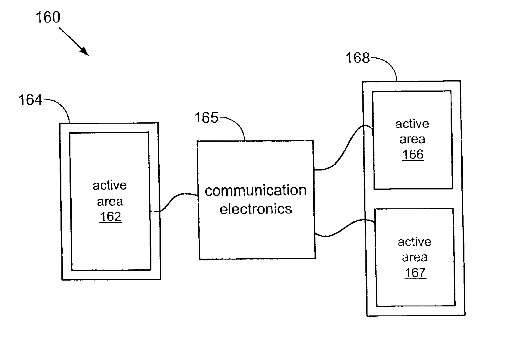
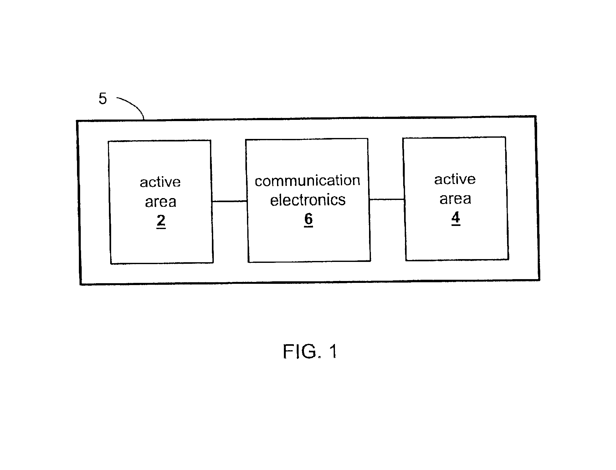
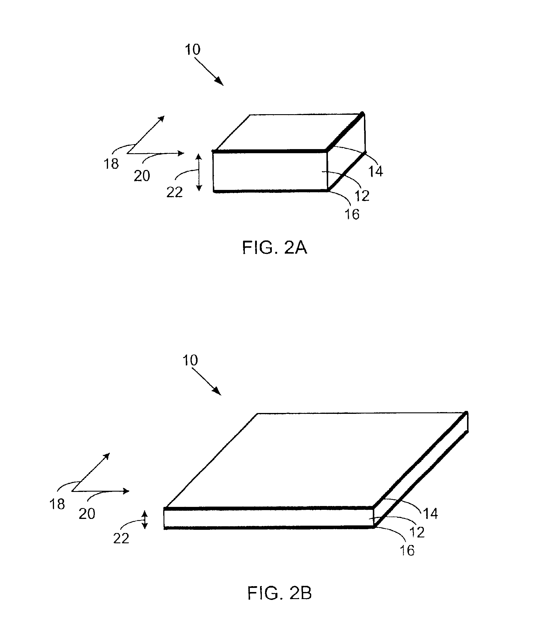
An electroactive polymer transducer converts between electrical and mechanical energy and comprises an electroactive polymer and at least two electrodes that provide or receive electrical energy to or from the polymer. The electroactive polymer transducer may be employed for one or more functions. When a suitable voltage is applied to electrodes in electrical communication with an electroactive polyme...


PUM


Abstract

The present invention relates to improved devices, systems and methods that convert between electrical and mechanical energy. An electroactive polymer transducer converts between electrical and mechanical energy. An active area is a portion of an electroactive polymer transducer. The active area comprises a portion of an electroactive polymer and at least two electrodes that provide or receive electrical energy to or from the portion. The present invention relates to transducers and devices comprising multiple active areas that are in electrically communication. More specifically, the present invention relates to master / slave arrangements for multiple active areas disposed on one or more electroactive polymers. In a master / slave arrangement, a first active area deflects (a ‘master’), and a second active area reacts (a ‘slave’). Communication electronics in electrical communication with electrodes for the first active area and in electrical communication with electrodes for the second active area transfer electrical energy between the two active areas.

Description

BACKGROUND OF THE INVENTIONThe present invention relates generally to electroactive polymer systems and methods that convert between electrical energy and mechanical energy. More particularly, the present invention relates to electroactive polymers, transducers and devices having multiple active areas that communicate electrical energy between them. The present invention also relates to methods of using electroactive polymers having multiple active areas.In many applications, it is desirable to convert between electrical energy and mechanical energy. Exemplary applications requiring conversion from electrical to mechanical energy include robotics, pumps, speakers, sensors, microfluidics, shoes, general automation, disk drives, and prosthetic devices. These applications include one or more transducers that convert electrical energy into mechanical work—on a macroscopic or microscopic level. Common actuator technologies, such as electromagnetic motors and solenoids, are not suitable f...

Claims


Application Information

Patent Timeline
Patent Type & Authority Patents(United States)
IPC IPC(8): H01L41/00H01L41/04H01L41/08H01L41/18H01L41/193
CPCA43B3/0005H01L41/042H01L41/08Y10S310/80H01L41/193A43B3/34H10N30/802H10N30/1071H10N30/857
Inventor PELRINE, RONALD E.KORNBLUH, ROY D.
Owner SRI INTERNATIONAL
Why Eureka
Try Eureka