Linear velocity sensor and method for reducing non-linearity of the sensor output signal

a linear velocity sensor and output signal technology, applied in the field of linear velocity sensors and methods for reducing nonlinearity of the sensor output signal, can solve the problems of insufficient accuracy to meet high-performance system requirements, additional complexity that incrementally adds to the cost of the sensor, and the limited technique of the first technique, so as to reduce the nonlinearity of the output signal

Inactive Publication Date: 2005-04-05
DELPHI TECH INC
View PDF11 Cites 42 Cited by
  • Summary
  • Abstract
  • Description
  • Claims
  • Application Information

AI Technical Summary

Benefits of technology

In another aspect thereof, the present invention further fulfills the foregoing needs by providing a method for reducing output signal non-linearity in a linear velocity sensor. The method allows providing a ferromagnetic housing that includes an opening. The method further allows disposing a spool in the housing. A slidable ferromagnetic rod is received in a bore in the spool. The ferromagnetic rod is extendable through the opening in the housing. A magnet is mounted at the one end of the rod distal from the opening when the rod is substantially inserted in the bore. A coil is wound on the spool. The method allows arranging the number of turns of the coil to taperingly increase as the coil progresses from an end of the spool proximate the opening in the housing to the opposite end of the spool. The arrangement for the number of turns of the coil is selected to reduce non-linearity of an output signal of the coil indicative of linear velocity.

Problems solved by technology

The first technique is somewhat limited since the derivative of the position signal generally introduces an unacceptable high level of noise to the resulting signal, and, consequently, lacks sufficient accuracy for meeting high-performance system requirements.
This would result in additional complexity that incrementally adds to the cost of the sensor.
Further, this technique may undesirably introduce relatively large phase delays.
Although this type of design has proven to be useful to generate velocity information, there are some issues that have yet to be addressed.
One issue that needs to be addressed is the fact that the output signal indicative of velocity information is undesirably dependent upon the plunger position.
Unfortunately, the size of the magnet used in various known configurations, may result in a relatively bulky sensor, which is generally undesirable for applications where spacing may be scarce.

Method used


Image

  • Linear velocity sensor and method for reducing non-linearity of the sensor output signal
  • Linear velocity sensor and method for reducing non-linearity of the sensor output signal
  • Linear velocity sensor and method for reducing non-linearity of the sensor output signal

Examples


Embodiment Construction

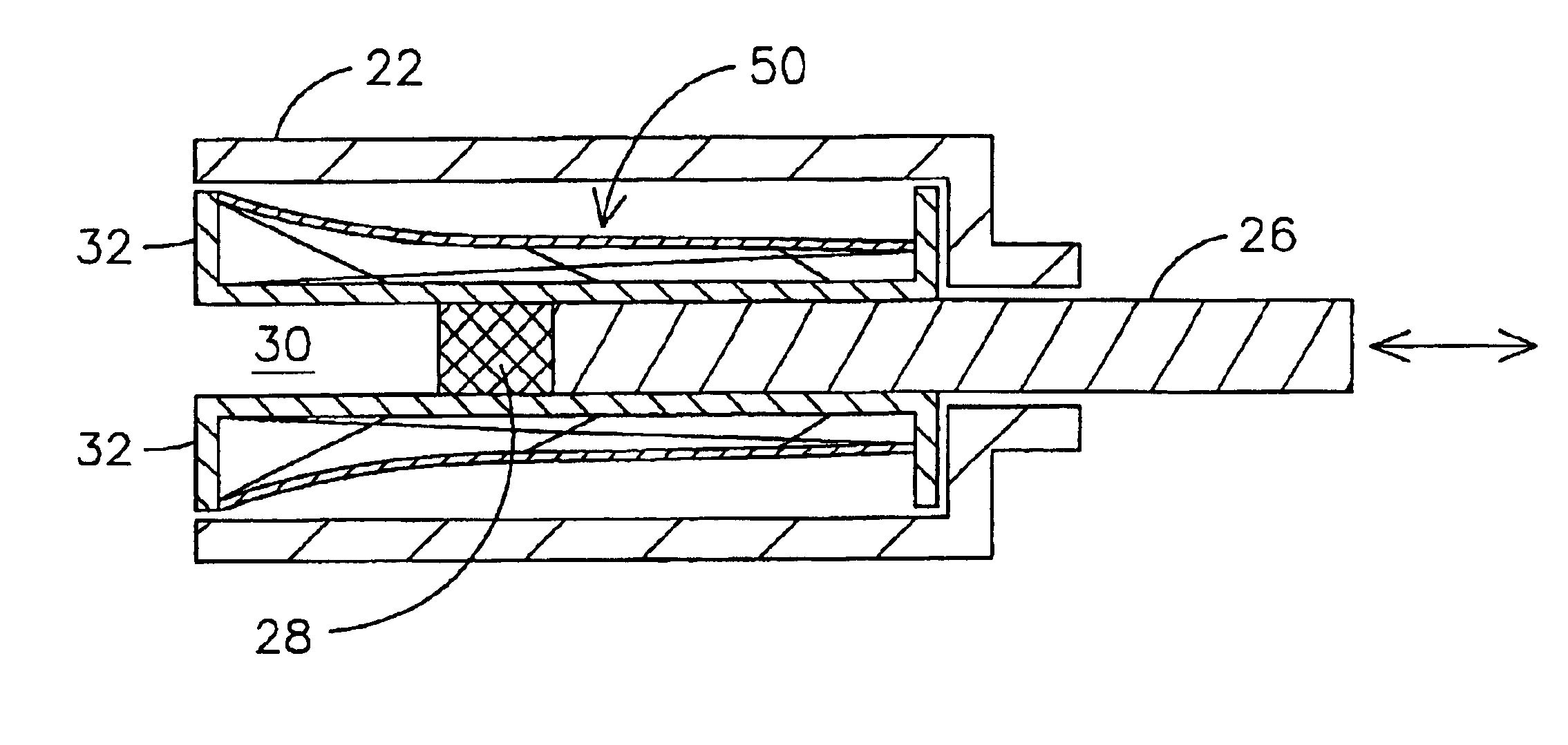
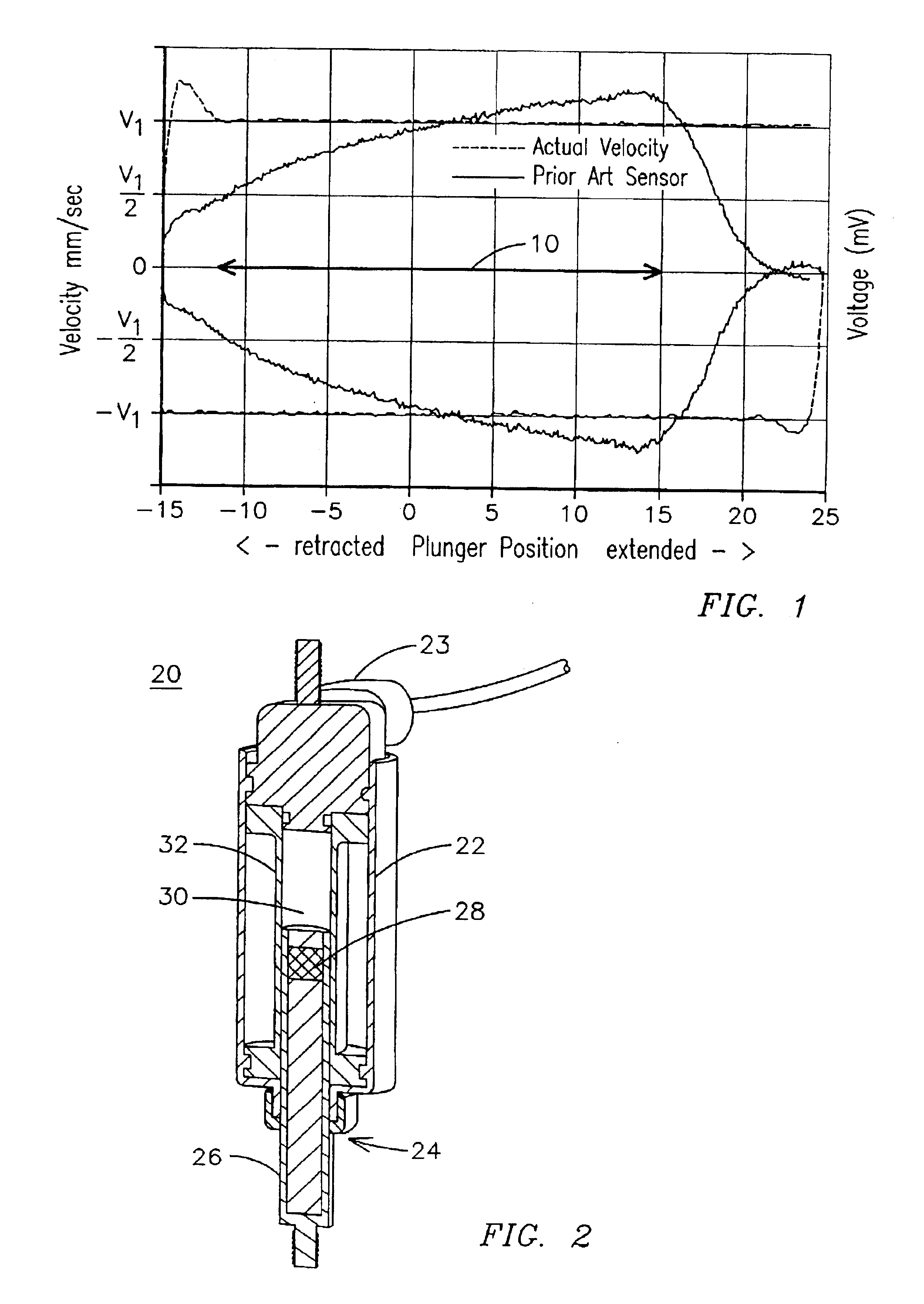
FIG. 2 illustrates an exemplary embodiment of a linear velocity sensor 20 embodying aspects of the present invention. As illustrated in FIG. 2, a ferromagnetic housing 22 includes an opening 24 for receiving a relatively small, ferromagnetic rod 26 with a magnet 28 mounted on one end of rod 26. The opposite end of housing 22 may be closed to the ferromagnetic plunger by the housing of an interface connector 23. As will be appreciated by those skilled in the art, since the housing is made up of ferromagnetic material, the housing functions as a flux concentrator of the magnetic flux from magnet 28. The rod essentially constitutes a plunger slidable or extendable through an axially-extending bore 30 in a spool 32.

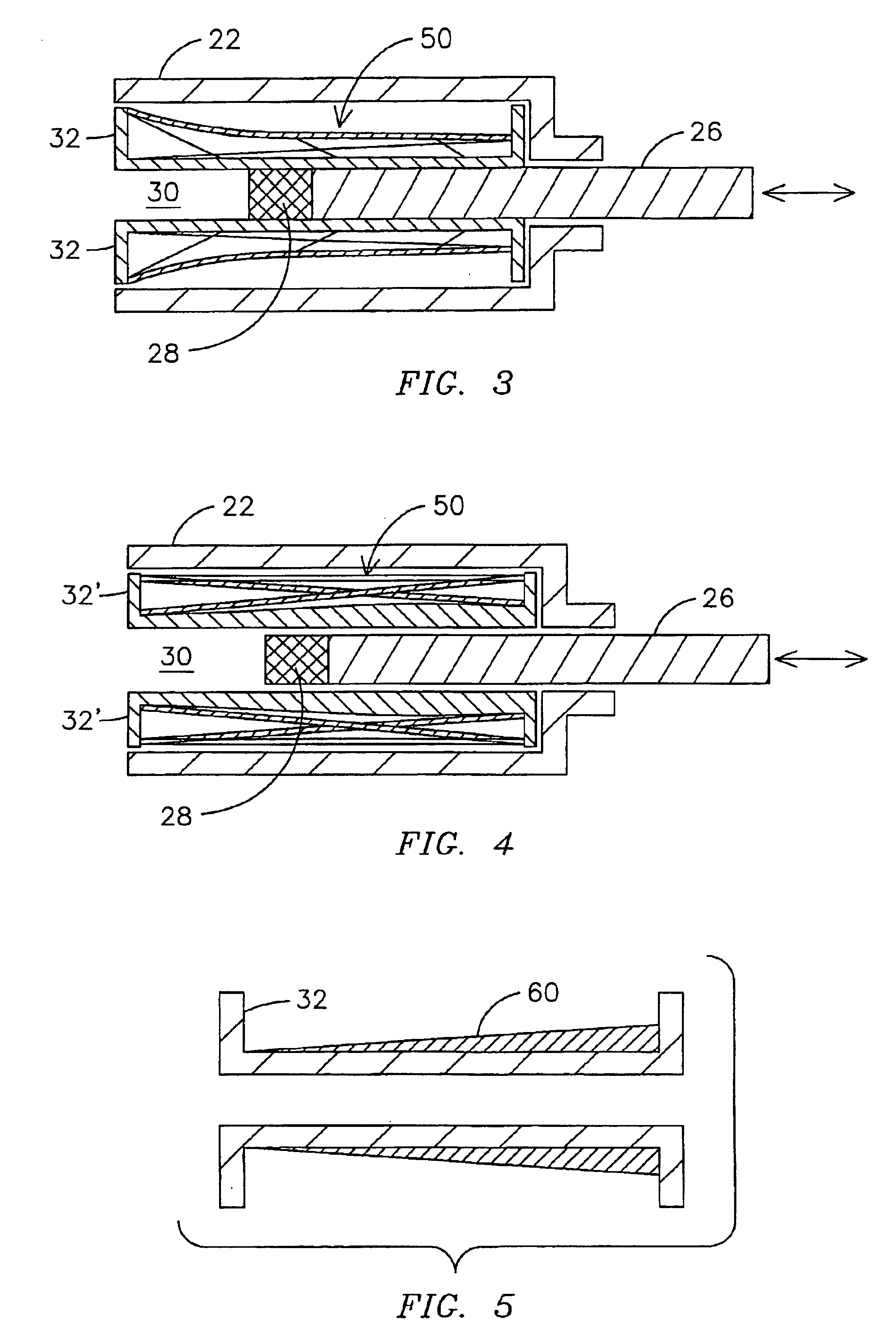
As shown in FIGS. 3 and 4, a coil 50 is wound around the spool 32. The coil is positioned between the plunger 26 and the housing 22, and, since each of such components is made up of ferromagnetic material, they jointly cooperate to form an electromagnetic magnetic circuit tha...


PUM


Abstract

Linear velocity sensor and method for reducing non-linearity in the output signal of the sensor are provided. The sensor comprises a ferromagnetic housing including an opening. The sensor further comprises a spool disposed in the housing. The spool includes a bore for receiving a slidable ferromagnetic rod. The ferromagnetic rod may be extendable through the opening in the housing. A magnet is mounted at the one end of the rod distal from the opening when the rod is substantially inserted in the bore. A coil is wound on the spool. The number of turns of the coil is arranged to taperingly increase as the coil progresses from an end of the spool proximate the opening in the housing to the opposite end of the spool. The tapering arrangement for the number of turns of the coil is selected to reduce non-linearity of an output signal of the coil indicative of linear velocity.

Description

BACKGROUND OF THE INVENTIONLinear velocity sensors (or simply velocity sensors) may play a very important role in the control of any mechanical system motion, or vibration that may be encountered by the mechanical system. For example, in the automotive industry, luxury vehicles are expected to provide “premium” performance, such as a smoother, or quieter ride, under a wide range of varying operational conditions. It is known that adaptive or proactive control may be provided to mechanically tune the suspension system, such as for the vehicle chassis, and / or the engine mounts, to accomplish this premium performance. Either an adaptive or a proactive vibration control system needs to sense system motion, such as relative displacements and relative velocities in order to select an appropriate vibration control strategy. Typically, a “linear relative velocity” sensor is used to provide the mechanical system velocity information for these types of control systems.There are presently a nu...

Claims


Application Information

Patent Timeline
Patent Type & Authority Patents(United States)
IPC IPC(8): G01P3/52G01P3/42
CPCG01P3/52
Inventor LIN, YINGJIETHOMSON, STEVEN DOUGLASPALFENIER, SAMUEL ROLAND
Owner DELPHI TECH INC
Why Eureka
Try Eureka