Liquid crystal display having a spontaneous polarization

a liquid crystal display and spontaneous polarization technology, applied in liquid crystal compositions, instruments, chemistry apparatus and processes, etc., can solve the problems of slow response speed, unsuitable display devices for personal computers, and unsuitable for animation pictures

Inactive Publication Date: 2005-04-05
FUJITSU LTD
View PDF6 Cites 2 Cited by
  • Summary
  • Abstract
  • Description
  • Claims
  • Application Information

AI Technical Summary

Benefits of technology

[0009]The present invention has been devised to solve the above-mentioned problems, and its objective is to provide a liquid crystal display which adjusts the magnitude of a spontaneous polarization and the relative dielectric constant of a liquid crystal to appropriate values so that it can drive the liquid crystal even by using a low applied voltage.
[0023]In this case, a liquid crystal having a spontaneous polarization, such as a ferroelectric liquid crystal and an anti-ferroelectric liquid crystal, is sealed between the pair of opposing substrates. Further, the magnitude of the spontaneous polarization of the liquid crystal sealed therein is more than ½ of a maximum quantity of charge that is to be injected to each pixel when the switching element is in an on-state. Therefore, as compared with conventional liquid crystal displays, the present liquid crystal display makes it possible to drive the liquid crystal with a lower applied voltage.
[0036]Moreover, another liquid crystal display of the present invention is further provided with a back-light having light sources for respectively emitting light rays of the three primary colors, and characterized in that these light sources are allowed to emit light rays in a time divided manner in synchronism with ON / OFF driving processes of the switching element so that it is possible to carry out a color display.

Problems solved by technology

However, they are not suitable for display devices for personal computers, etc. which carry out a multi-color or full-color display.
Although those of the STN type have comparatively low manufacturing costs, they are susceptible to cross-talk, and comparatively slow in response speeds; therefore, they are not suitable for display for animation pictures.
For this reason, those of the TFT-TN type have greater power consumption due to the back-light, resulting in a problem in use of carrying battery power-source.
Moreover, the TFT-TN type have other problems with the response speed, particularly slow in response speed for displaying half tones, narrow viewing angle, difficulty in adjusting the color balance, etc.
However, in the liquid crystal display using a liquid crystal having a spontaneous polarization, such as a ferroelectric liquid crystal or an anti-ferroelectric liquid crystal, that is driven by using a switching element, there is a problem in which the driving operation requires a greater voltage.

Method used


Image

  • Liquid crystal display having a spontaneous polarization
  • Liquid crystal display having a spontaneous polarization
  • Liquid crystal display having a spontaneous polarization

Examples


example 1

[0061]In Example 1, the ferroelectric liquid crystal sealed in the liquid crystal panel has relative dielectric constant of approximately 6 and a magnitude of the spontaneous polarization of 13.5 nC / cm2.

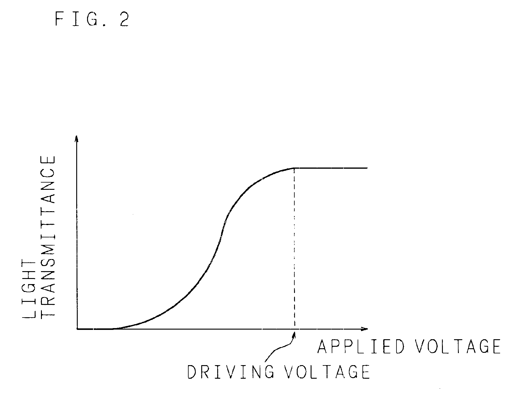
[0062]Then, a voltage was applied to the liquid crystal through the switching element of the TFT 11 so that the applied voltage and the light transmittance were measured. Consequently, as shown in FIG. 7, the light transmittance varied in proportion to the applied voltage and came to be saturated at approximately 10 V. Therefore, the liquid crystal display of the present example can be driven by using a liquid crystal driver IC of an output voltage of ±10 V.

[0063]Here, in the case when a voltage of 10 V was applied during the ON-state of the switching element, the quantity of charge injected to each pixel was 29 nC / cm2.

[0064]Next, an explanation will be given of the displaying operation of the liquid crystal display of the present invention in accordance with Example 1. In the liquid...

example 2

[0067]In Example 2, the ferroelectric liquid crystal sealed in the liquid crystal panel has a relative dielectric constant of approximately 6 and a magnitude of the spontaneous polarization of 8.2 nC / cm2.

[0068]Then, a voltage was applied to the liquid crystal through the switching element of the TFT 11 so that the applied voltage and the light transmittance were measured. Consequently, as shown in FIG. 8, the light transmittance varied in proportion to the applied voltage and came to be saturated at approximately 6.5 V. Therefore, the liquid crystal display of the present example can be driven by using a liquid crystal driver IC of an output voltage of ±7 V.

[0069]Here, in the case when a voltage of 6.5 V was applied during the ON-state of the switching element, the quantity of charge injected to each pixel was 19.7 nC / cm2.

example 3

[0070]In Example 3, the ferroelectric liquid crystal sealed in the liquid crystal panel has a relative dielectric constant of approximately 5 and a magnitude of the spontaneous polarization of 6.3 nC / cm2.

[0071]Then, a voltage was applied to the liquid crystal through the switching element of the TFT 11 so that the applied voltage and the light transmittance were measured. Consequently, as shown in FIG. 9, the light transmittance varied in proportion to the applied voltage and came to be saturated at approximately 5 V. Therefore, the liquid crystal display of the present example can be driven by using a liquid crystal driver IC of an output voltage of ±5 V.

[0072]Here, in the case when a voltage of 5 V was applied during the ON-state of the switching element, the quantity of charge injected to each pixel was 14 nC / cm2.


PUM

PropertyMeasurementUnit
relative dielectric constantaaaaaaaaaa
light transmittanceaaaaaaaaaa
relative dielectric constantaaaaaaaaaa

Abstract

A liquid crystal display in which a liquid crystal, which has a spontaneous polarization of a magnitude of not more than ½ of a maximum quantity of charge that is injected to each pixel when the switching element is turned on, is filled between alignment films formed on respective glass substrates, so as to form a liquid crystal layer thereby to drive the liquid crystal by using a lower applied voltage.

Description

BACKGROUND OF THE INVENTION[0002]The present invention relates to a liquid crystal display, and more particularly to a liquid crystal display using a liquid crystal having a spontaneous polarization.[0003]Along with the recent developments of the so-called office automation (OA), OA apparatuses, typically exemplified by word-processors and personal computers, have been widely used. As such OA apparatuses have become prevalent in offices, there have been ever-increasing demands for portable-type OA apparatuses that can be used in offices as well as outdoors; and there have been also demands for small-size and light-weight of such apparatuses. Here, liquid crystal displays have come to be widely used as one of the means to achieve such an objective. Liquid crystal displays not only achieve small-size and light-weight, but also include an indispensable technique in an attempt to achieve low power consumption in portable OA apparatuses that are driven by batteries.[0004]The liquid cryst...

Claims


Application Information

Patent Timeline
Patent Type & Authority Patents(United States)
IPC IPC(8): G02F1/137G02F1/13G02F1/133G02F1/141G09G3/36
CPCG02F1/141G09G3/3648G09G2310/06G02F1/133
Inventor YOSHIHARA, TOSHIAKIMAKINO, TETSUYASHIROTO, HIRONORIKIYOTA, YOSHINORI
Owner FUJITSU LTD
Why Eureka
Try Eureka