Motor control apparatus, disk apparatus and acceleration detection device

a technology of acceleration detection and motor control, which is applied in the direction of digital signal error detection/correction, instruments, recording signal processing, etc., can solve the problems of limited temperature rise, large amount of heat, and large amount of heat generated by motors, and achieve excellent heat quantity calculation function, prevent inconvenience caused, and high performance

Inactive Publication Date: 2005-04-05
PANASONIC CORP
View PDF4 Cites 17 Cited by
  • Summary
  • Abstract
  • Description
  • Claims
  • Application Information

AI Technical Summary

Benefits of technology

In one embodiment of the invention, the motor controller sets the restriction value of the driving current to be higher as an intended rotation speed of the motor increases.
Thus, the invention described herein makes possible the advantages of providing a motor control apparatus for preventing inconveniences caused by overheating while guaranteeing high performance by controlling a motor operation at appropriate timing with a superb heat quantity calculation function, a disk apparatus including such a motor control apparatus, and high precision acceleration detection device and speed detection device.

Problems solved by technology

Therefore, the motor coil in an apparatus incorporating a motor which is rotated with rapid acceleration or deceleration generates a huge amount of heat, and accordingly it is required to prevent a temperature rise caused by the heat generation.
These motors generate a huge quantity of heat.
Thus, the temperature rise is restricted.
However, the conventional magnetic disk apparatus 101 has a problem in that the precision of calculation of the heat quantity ΔQv1 is significantly poor.
However, these two are not necessarily proportional to each other.
As a result, it is difficult to raise the precision of current detection.
For the above-described reasons, the electric current icalc calculated by the conventional method based on a value iv1 has a large error with respect to an actual electric current ireal.
Thus, the precision of temperature prediction is very poor.
Since the VCM 106 is controlled by the result of temperature prediction having such a poor precision, the following inconveniences occur: the start of the seek operation is not delayed although the actual temperature exceeds the reference value T1′, which results in overheating or destruction of the VCM 106; and the start of the seek operation is delayed although the actual temperature is sufficiently lower than the reference value T1′, which lowers the performance of the magnetic disk apparatus 101.
A direct detection of the actual electric current i at a high precision requires a complicated structure and undesirably raises the cost of components and the number of steps of assembly.

Method used


Image

  • Motor control apparatus, disk apparatus and acceleration detection device
  • Motor control apparatus, disk apparatus and acceleration detection device
  • Motor control apparatus, disk apparatus and acceleration detection device

Examples


example 1

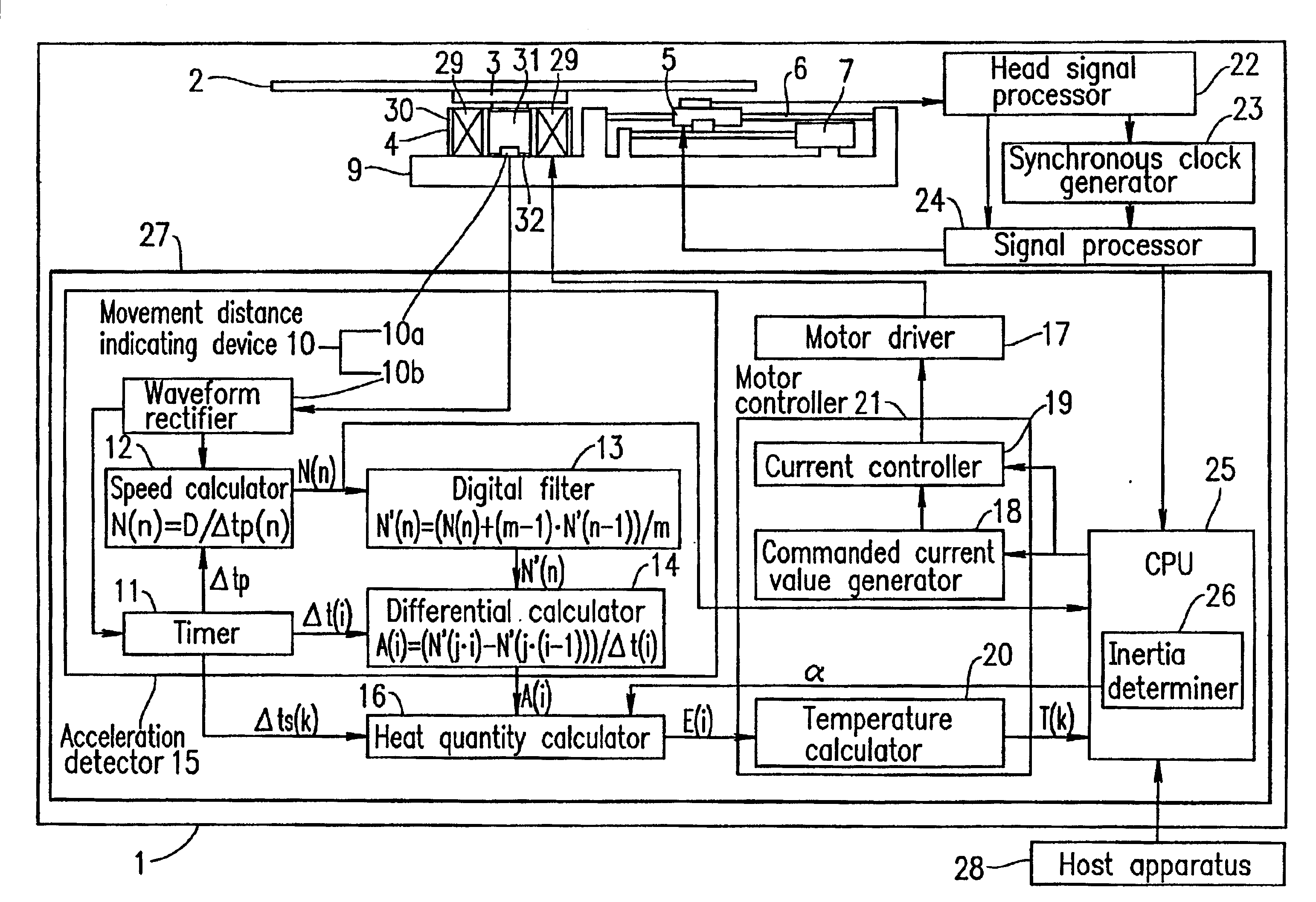
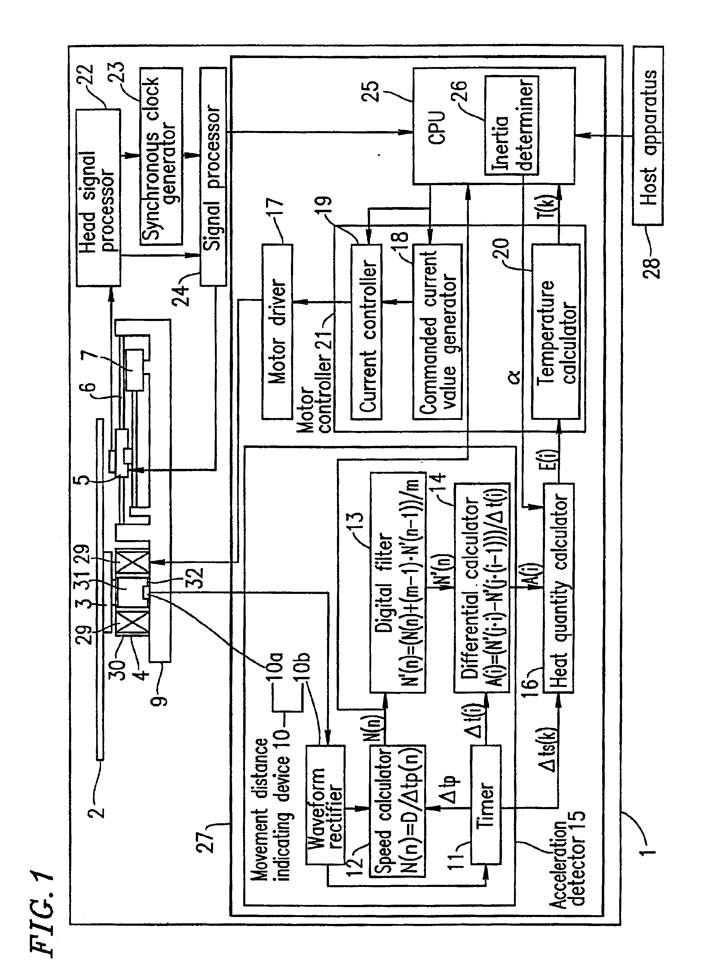
FIG. 1 is a schematic diagram illustrating a structure of an optical disk apparatus 1 according to a first example of the present invention.

The optical disk apparatus 1 includes a motor control device 27, a turntable 3 on which an optical disk 2 is placed, a disk motor 4 for rotating the turntable 3 and the optical disk 2, an optical head 5, a guide shaft 6 for supporting the optical head 5 so as to be movable in a radial direction of the optical disk 2, a head transporting motor 7 for supplying a driving force to transport the optical head 5 supported by the guide shaft 6 to a desired radial position above the optical disk 2, a chassis 9, a head signal processing circuit 22, a synchronous clock generator 23, and a signal processor 24.

The disk motor 4 includes a stator section 30 having a motor coil 29 which is supplied with an electric current and thus generates an electromagnetic field, and a rotor section 32 having a ring-shaped magnet 31. The magnet 31 includes positive and nega...

example 2

FIG. 6 is a schematic diagram illustrating a structure of an optical disk apparatus 41 according to a second example of the present invention.

The optical disk apparatus 41 is different from the optical disk apparatus 1 (FIG. 1) according to the first example in that an acceleration detector (acceleration detection device) 42 of a motor control device 43 of the optical disk apparatus 41 does not include a digital filter. Except for this point, the optical disk apparatus 41 has the same structure as that of the optical disk apparatus 1. Identical elements previously discussed with respect to FIG. 1 bear identical reference numerals and the descriptions thereof will be omitted.

The acceleration detector 42 operates in the following manner.

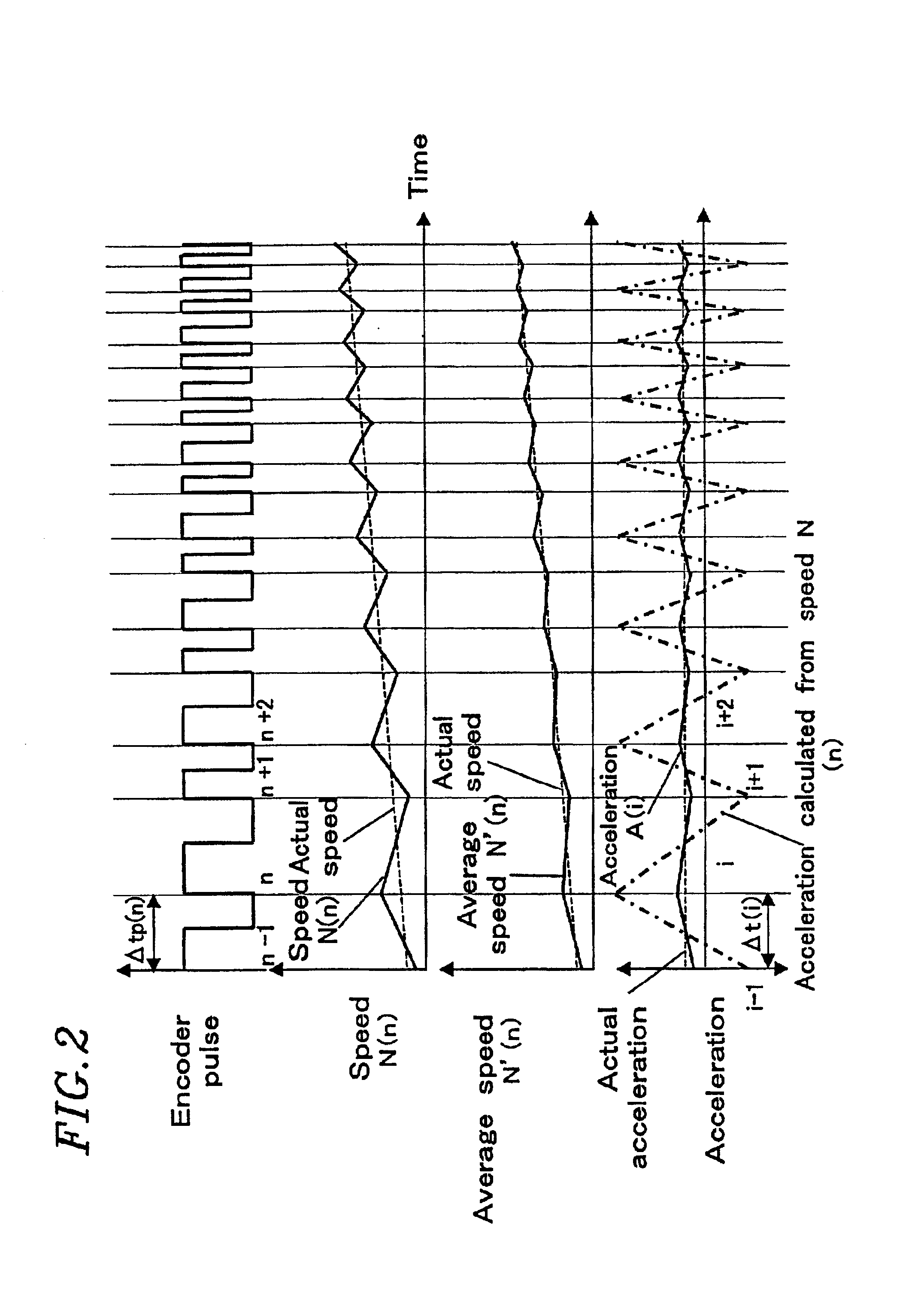
The speed calculator 12 and the differential calculator 14 calculate the acceleration A(i) from the speed N(n) of the disk motor 4 by expression (1) shown above and expression (2) shown below, and output the acceleration A(i) to the heat quantity calcu...


PUM

PropertyMeasurementUnit
resistanceaaaaaaaaaa
unit angleaaaaaaaaaa
rotation angleaaaaaaaaaa

Abstract

A motor controlling device includes an acceleration detector for detecting an acceleration of a motor; a motor driver for supplying a driving current to the motor; a heat quantity calculator for calculating a heat quantity generated in the motor at least based on an output from the acceleration detector; and a motor controller for controlling the motor driver based on the heat quantity.

Description

BACKGROUND OF THE INVENTION1. Field of the InventionThe present invention relates to a motor control device for preventing a temperature rise of an optical disk apparatus including the motor control device, based on a predicted temperature rise of a motor or the apparatus including the motor, by calculating the quantity of heat generated by the motor: and a disk apparatus including such a motor control device.2. Description of the Related ArtMotors have conventionally been incorporated in various types of apparatus. Motors rotate a driven target by causing an electric current to flow through a motor coil and thus generating a rotation force (i.e., torque) corresponding to the size of the electric current. When a motor is rotated at a constant speed, it is sufficient to generate a torque corresponding to a load on a bearing or the like. Accordingly, only a small amount of current is required. However, when the speed of rotation needs to be rapidly accelerated or decelerated, a torque...

Claims


Application Information

Patent Timeline
Patent Type & Authority Patents(United States)
IPC IPC(8): G11B19/28G11B7/085
CPCG11B19/28G11B7/08505
Inventor KAJINO, OSAMUMUSHIKA, YOSHIHIROISHIBASHI, HIROSHIGE
Owner PANASONIC CORP
Why Eureka
Try Eureka