
Method and apparatus for multiprotocol switching and routing

a multi-protocol, switching and routing technology, applied in data switching networks, multiplex communication, digital transmission, etc., can solve the problems of limiting the rate at which traffic can be sent over the network, requiring substantial processing overhead, and not being able to interconnect routed networks and network segments running multiple protocols, etc., to achieve efficient partitioning, reduce processing overhead, and reduce costs

Inactive Publication Date: 2005-04-05
INTEL CORP
View PDF21 Cites 126 Cited by
  • Summary
  • Abstract
  • Description
  • Claims
  • Application Information

AI Technical Summary

Benefits of technology

An object of the invention is to provide a method and apparatus that can forward packets to their destination at high throughput rates with substantially less processing overheads.
Another object of the invention is to provide a method and apparatus that can both switch and route packets with the same minimal processing overhead.
Another object of the invention is to provide a method and apparatus capable of multiprotocol wire-speed switching and routing that is inexpensive to implement.
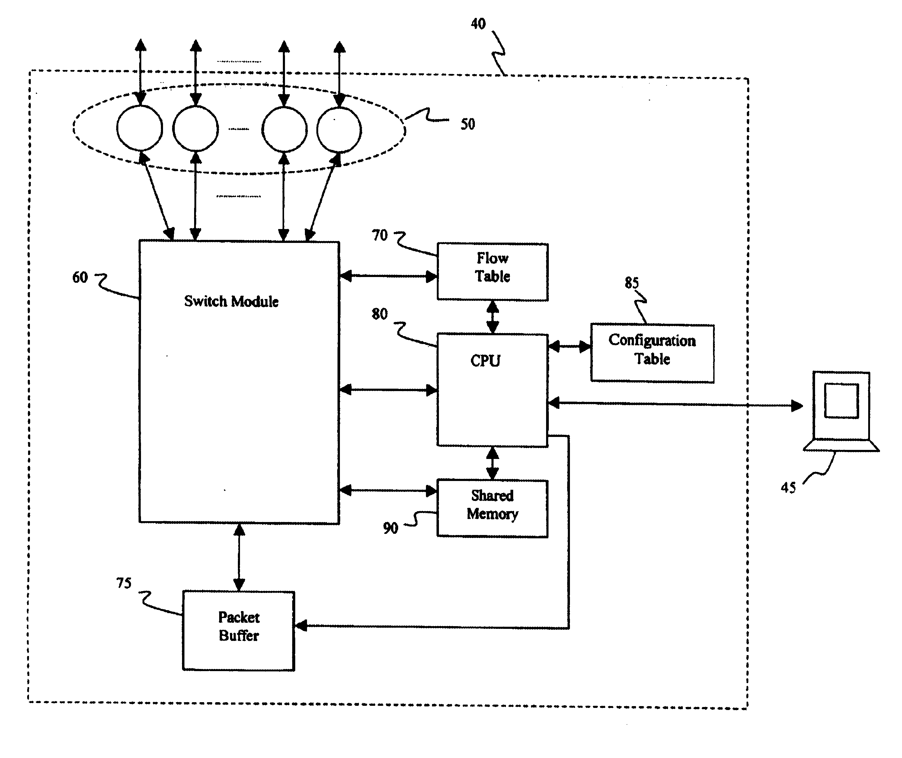
The present invention fulfills these objects, among others, by providing a method and apparatus for performing multiprotocol switching and routing. Incoming data-packets are examined and the flow (i.e., source node, the application running on the source node that is initiating the connection and generating the packets, destination node and the application on the destination node to which the traffic is destined) with which they are associated is determined. A flow table contains forwarding information that can be applied to the flow. If an entry is not present in the table for the particular flow, the packet is forwarded to the CPU to be processed. The CPU extracts the flow information from the packet and updates the table with forwarding information to be applied to all future packets belonging to the same flow. When the forwarding information is already present in the table, packets can thus be forwarded in hardware with no processor intervention at wire-speed. A dedicated ASIC is preferably employed to contain the table, as well as the engine for examining the packets and forwarding them according to the information stored in the flow tables. Decision-making tasks are thus more efficiently partitioned between the switch and the CPU so as to minimize processing overhead, while providing an inexpensive multiprotocol solution.

Problems solved by technology

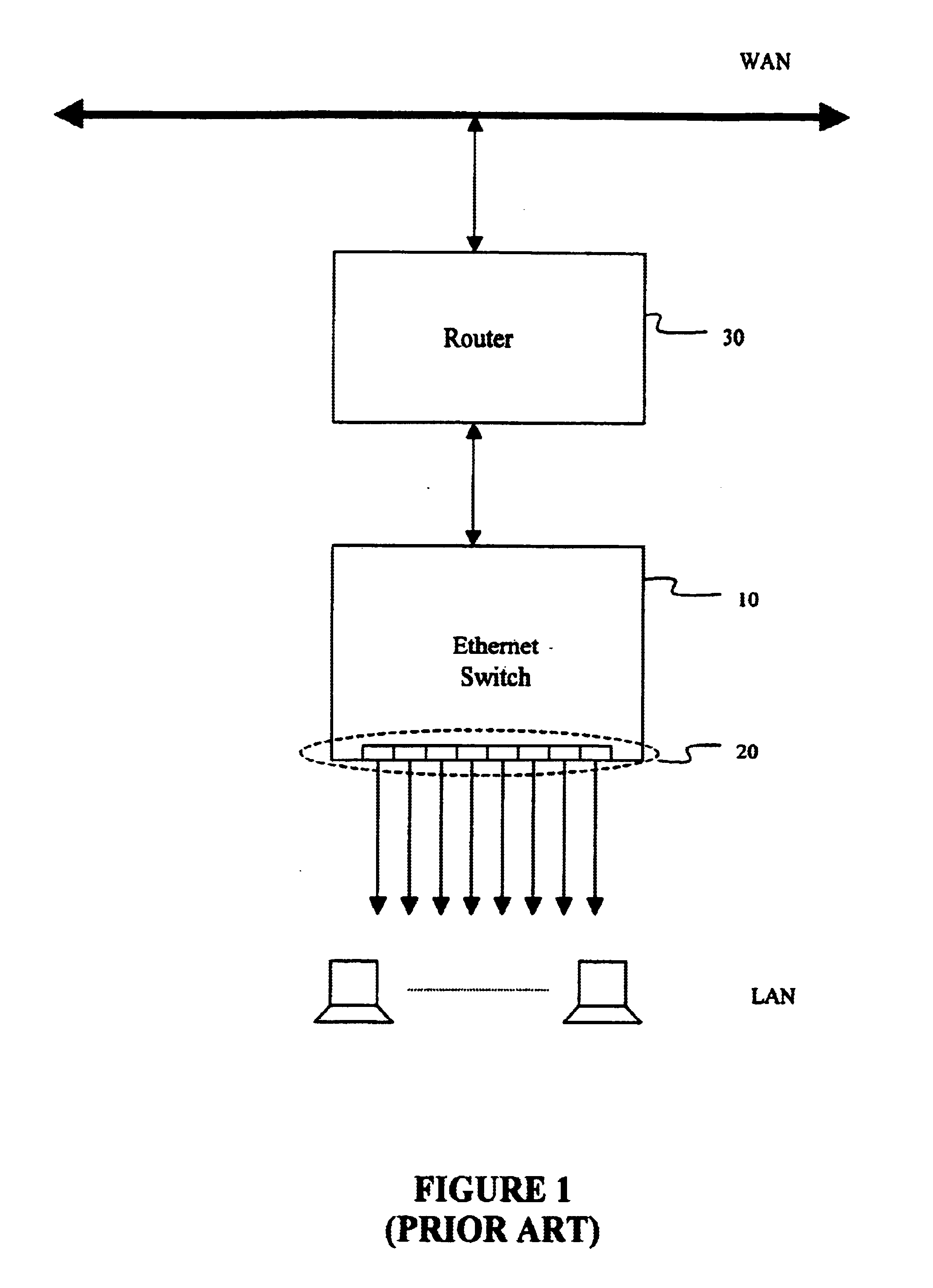
Both of these types of switches are good for the specific operation for which they are designed, but they can not be used to interconnect routed networks and network segments running multiple protocols such as IP and IPX that are fairly common on networks today.
Although such CPU-assisted routers are able to handle the various routing protocols encountered, the processing overhead they require is substantial and this limits the rate at which traffic can be sent over the network.
Since Layer 2 switches use Ethernet addresses only, they are unable to provide connectivity between multiple IP or IPX networks or subnets.
Therefore they are much more expensive than layer 2 switches.
Conventional routers, moreover, do not perform switching operations and therefore can not be used to connect networks that run non-routable protocols such as NetBios, DLC / LLC and LAT.
Routers also can not be used to connect multiple nodes belonging to the same IP or IPX networks since each router interface must belong to a different IP or IPX network.
However, these schemes typically support only limited numbers of protocols, may require reconfiguration of end stations and still may require external routers.

Method used


Image

  • Method and apparatus for multiprotocol switching and routing
  • Method and apparatus for multiprotocol switching and routing
  • Method and apparatus for multiprotocol switching and routing

Examples


Embodiment Construction

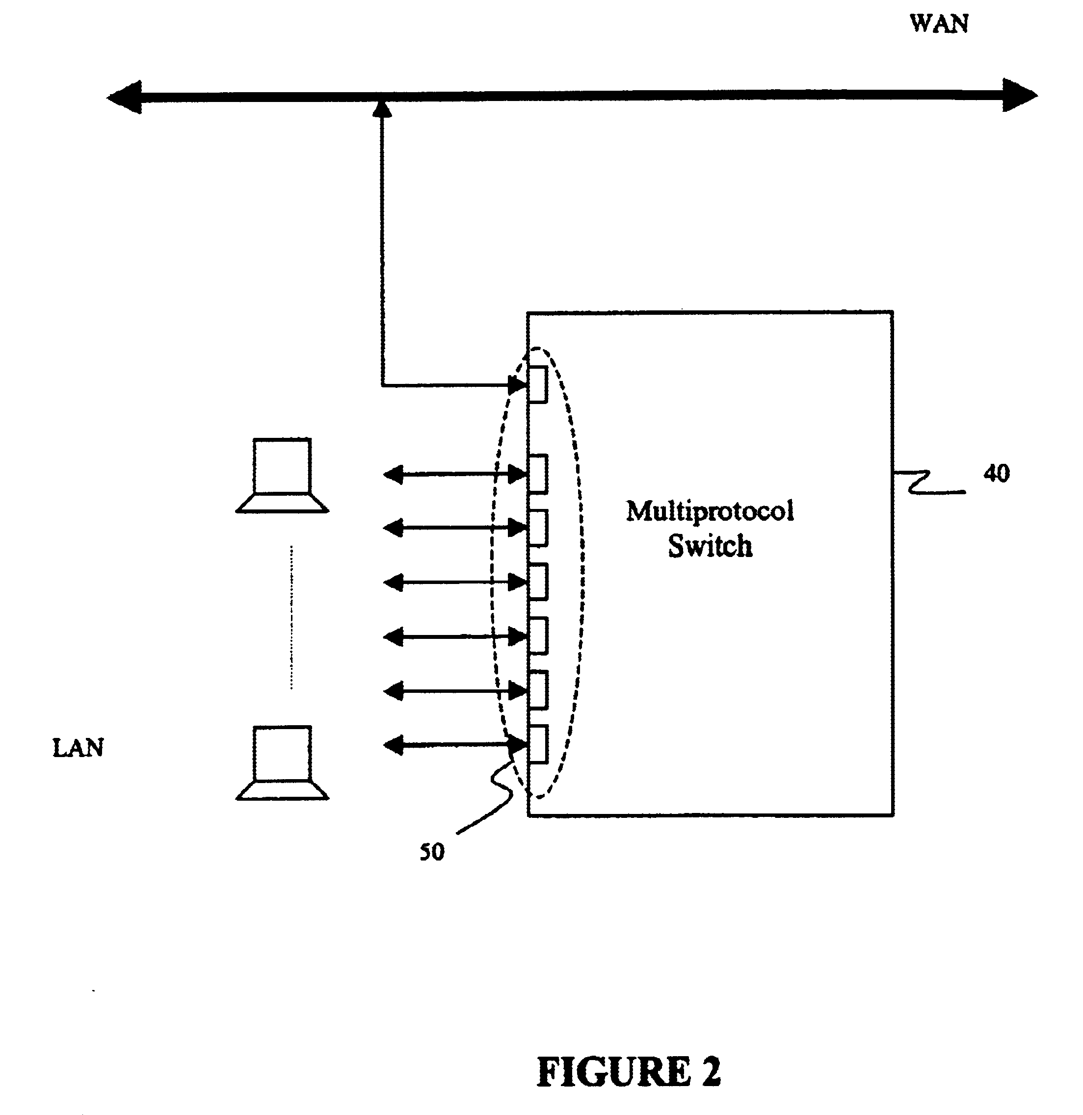
FIG. 2 is a block diagram illustrating an architecture for performing multiprotocol routing in accordance with the principles of the invention. It includes a multiprotocol switch 40 having N input / output ports 50-1 . . . 50-N. In accordance with an object of the invention, as illustrated in FIG. 2, the input / output ports can be attached to nodes or they can be attached to different network segments or different networks in a local area network (LAN) directly or via routers. The novel ability of the multiprotocol switch of the present invention to forward packets among and between local nodes and external networks attached to it will be described below.

FIG. 3 further illustrates a multiprotocol switch 40 in accordance with the principles of the invention. In addition to input / output ports 50, it includes a switch module 60 and a flow table 70. Switch module 60 further communicates with a packet buffer 75, a CPU 80 and a shared memory 90. Flow table 70 and shared memory 90 are mapped ...


PUM


Abstract

A packet forwarding method and apparatus performs multiprotocol routing (for IP and IPX protocols) and switching. Incoming data packets are examined and the flow (i.e., source and destination addresses and source and destination socket numbers) with which they are associated is determined. A flow table contains forwarding information that can be applied to the flow. If an entry is not present in the table for the particular flow, the packet is forwarded to the CPU to be processed. The CPU can then update the table with new forwarding information to be applied to all future packets belonging to the same flow. When the forwarding information is already present in the table, packets can thus be forwarded at wire speed. A dedicated ASIC is preferably employed to contain the table, as well as the engine for examining the packets and forwarding them according to the stored information. Decision-making tasks are thus more efficiently partitioned between the switch and the CPU so as to minimize processing overhead.

Description

BACKGROUND OF THE INVENTION1. Field of the InventionThe present invention relates to packet switches and routers, and more particularly, to a switching and routing method and apparatus capable of performing wire-speed switching and routing of data packets associated with a variety of network traffic protocols.2. Description of the Related ArtConventional network traffic is formatted into packets that are sent through the network according to destination addresses programmed in the packet header. The networking equipment used to forward such packets through a network includes routers, Layer 2 switches and Layer 3 switches. Each of these different types of equipment operate at different layers in the seven-layer OSI model. That is, for example, Layer 2 switches examine the Ethernet (MAC) addresses embedded in the packet to make forwarding decisions, while Layer 3 or “IP” switches examine the IP addresses embedded in the packet to make forwarding decisions. Both of these types of switc...

Claims


Application Information

Patent Timeline
Patent Type & Authority Patents(United States)
IPC IPC(8): H04L12/46
CPCH04L12/4625
Inventor HEGDE, GOPAL DATTARAY
Owner INTEL CORP
Learn More