Vehicle positioning apparatus and method

Inactive Publication Date: 2005-04-05
MERCK & CO INC +1
View PDF18 Cites 119 Cited by
  • Summary
  • Abstract
  • Description
  • Claims
  • Application Information

AI Technical Summary

Benefits of technology

Preferably steerage feedback sensors operative to generate steerage feedback signals indicative of orientation of said steerable wheels or tracks,

Problems solved by technology

However if the passes are too close together, that is closer than the working width of the implement, then a problem arises in that over consecutive passes the implement is partially back over a strip of paddock processed during the last pass.
Hence an undesirable overlap occurs.
Alternatively, if the passes are too far apart then another problem arises in that a strip of unprocessed paddock is left between consecutive passes of the implement.
Factors such as varying seasonal conditions, undulating terrain, driver fatigue and such like may result in the driver inaccurately estimating the correct starting point of a pass, so that the offset from an adjacent pass is incorrect, or may result in the

Method used


Image

  • Vehicle positioning apparatus and method
  • Vehicle positioning apparatus and method
  • Vehicle positioning apparatus and method

Examples


Embodiment Construction

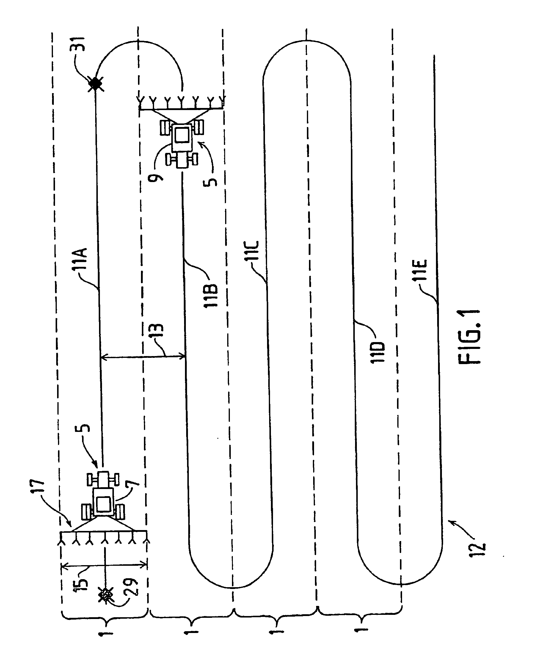
With reference to FIG. 1, there is depicted a plan view of a paddock including parallel rows 1 produced by passes of tractor 5 back and forth across the paddock. It is desired that tractor 5, shown at positions 7 and 9 travels back and forth across the paddock along path 12. It will be noted that the straight-line segments, or “waylines”11A-11E of path 12 are all parallel and are offset from each other a distance 13 which is identical to the working width 15 of implement 17. By offsetting waylines 11A-11E from each other by the working width of the implement, consecutive passes of the implement do not overlap each other nor is there a strip of unprocessed paddock left between adjacent rows.

Referring now to FIG. 2 there is depicted a schematic representation of the basic elements of a guidance assist system 10 according to an embodiment of the present invention. Guidance assist system 10 is intended for incorporation into an agricultural vehicle such as tractor 5.

Guidance assist syst...


PUM


Abstract

There is disclosed a guidance assisting apparatus for aiding in the guidance of an agricultural vehicle (5) over arable land. The apparatus makes use of a GPS positional receiver (81) in order to determine if the vehicle (5) is overlapping previous passes of a paddock thereby reducing the likelihood of strips of land being double processed or left unprocessed. Guidance may be provided by a visual display or by power assisted steering.

Description

FIELD OF THE INVENTIONThe present invention is concerned with means and methods for increasing the efficiency of mechanised crop farming.BACKGROUND OF THE INVENTION AND SURVEY OF PRIOR ARTCrop farming typically involves the sowing, fertilisation and harvesting of crop plants in a paddock. Modern day crop farming makes extensive use of automotive farm machinery, such as tractors, which are used to pull field-working implements, such as ploughs or fertilising rigs etc. The width of the field-working implement is generally greater than the width of the tractor. In operation the tractor is driven up and down the paddock in passes which follow parallel lines. However if the passes are too close together, that is closer than the working width of the implement, then a problem arises in that over consecutive passes the implement is partially back over a strip of paddock processed during the last pass. Hence an undesirable overlap occurs. Alternatively, if the passes are too far apart then a...

Claims


Application Information

Patent Timeline
IPC IPC(8): A01B69/00G01C21/00G05D1/02
CPCA01B69/00G01C21/00G05D1/0278G05D2201/0201G05D1/027G05D1/0219
Inventor MAILER, ROBERT LINDSAY
Owner MERCK & CO INC
Why Eureka
Try Eureka