Supercharge Your Innovation With Domain-Expert AI Agents!

Measurement of inductance using a digital storage oscilloscope under real-time operating environments

a digital storage and oscilloscope technology, applied in the direction of inductance measurement, resistance/reactance/impedence, instruments, etc., can solve the problems of complex process of plotting b-h curve and measuring curve slope, and none of the digital storage oscilloscopes available in the market have a scope resident feature capable of analyzing the plo

Inactive Publication Date: 2005-04-05
TEKTRONIX INC
View PDF2 Cites 11 Cited by
  • Summary
  • Abstract
  • Description
  • Claims
  • Application Information

AI Technical Summary

Benefits of technology

The present invention provides a method and apparatus for measuring inductance by analyzing current and voltage waveform data. This allows for the determination of edge and slope parameters for each data cycle, as well as the calculation of proportional magnetic flux and current. Ultimately, an inductance value can be calculated based on these parameters. This invention overcomes the disadvantages of previous methods and provides a more accurate and reliable way to measure inductance.

Problems solved by technology

Plotting the B-H curve and measuring the slope of the curve is a complex process, since each step requires careful and correct manual analysis.
Currently, none of the digital storage oscilloscopes available in the market have a scope resident feature capable of analyzing the plot data and giving the results extracted from the plot.

Method used


Image

  • Measurement of inductance using a digital storage oscilloscope under real-time operating environments
  • Measurement of inductance using a digital storage oscilloscope under real-time operating environments
  • Measurement of inductance using a digital storage oscilloscope under real-time operating environments

Examples


Embodiment Construction

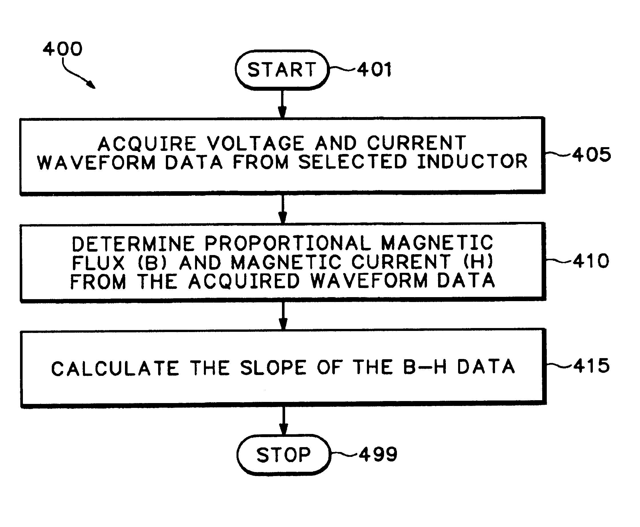
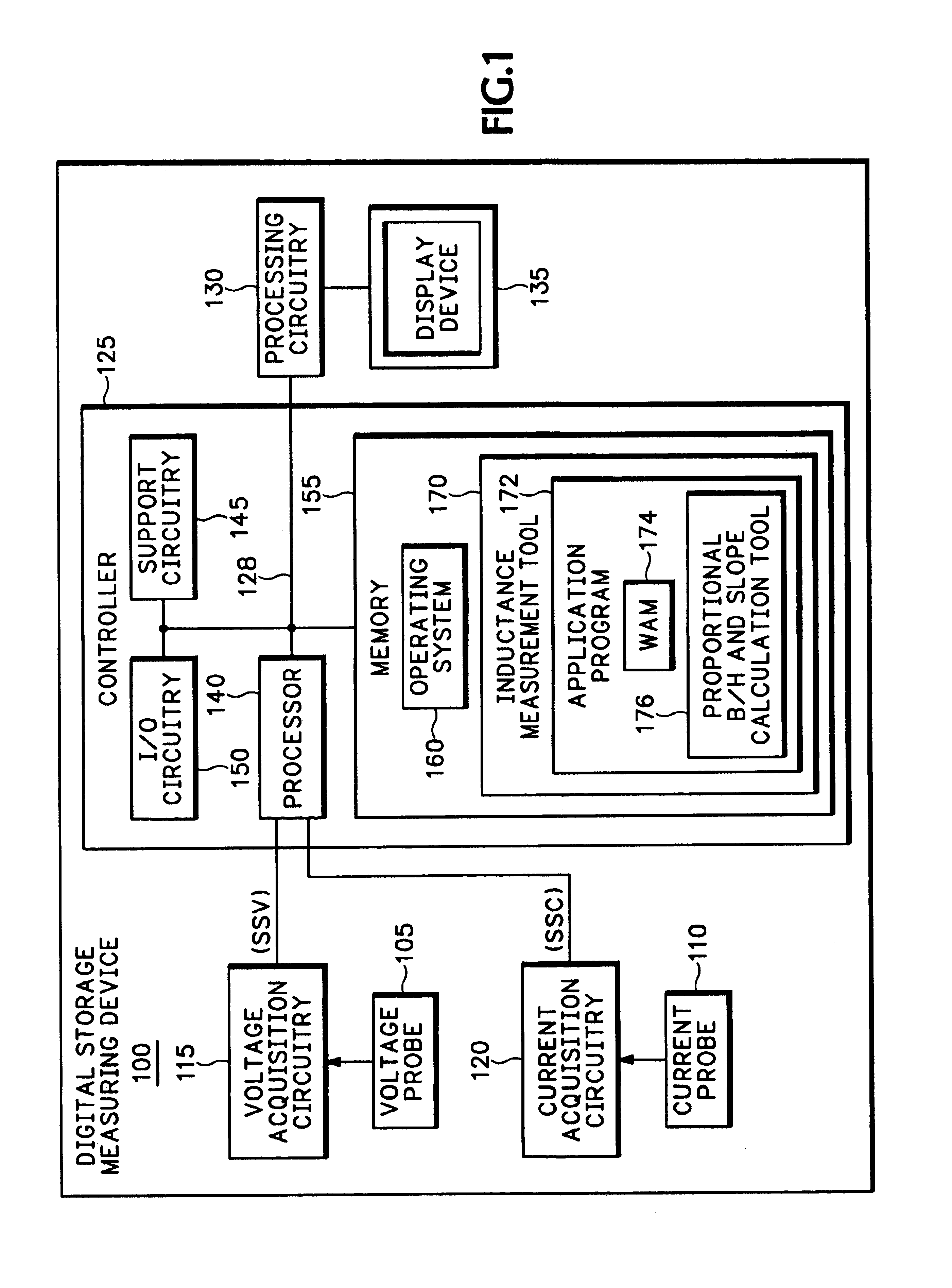
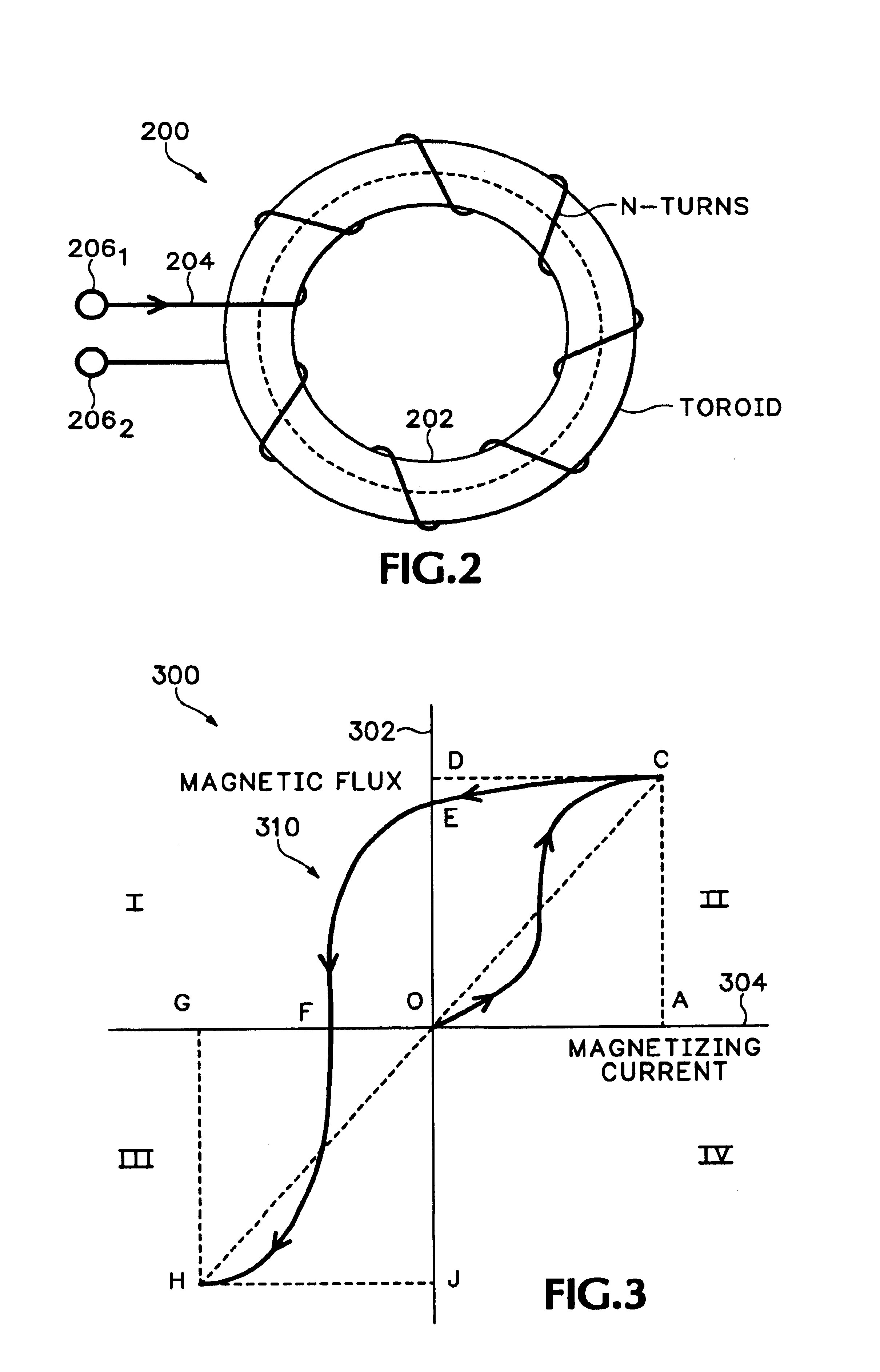
The present invention comprises a method and apparatus for performing in-circuit inductance measurements, as well as observing the behavior of an inductor in a real-time operating environment. Specifically, voltage and current waveform data associated with an inductive device (e.g., of a switching power supply) is acquired to determine the average (proportional) magnetizing flux (B) and magnetizing current (H) inductance of such inductive device under real-time operating conditions. The slope of the proportional B-H data is then calculated to determine the real-time inductance of the inductor being measured.

The present invention is discussed in terms of an inductance measurement software tool, such as a TDSPWR2 inductance measurement tool produced by Tektronix, Inc. of Beaverton, Oreg. The exemplary power-measurement program tool is installed (i.e., stored) in local memory of a digitizing test and measurement device, such as a digital storage oscilloscope (DSO) (e.g., a Tektronix, I...


PUM


Abstract

A method and apparatus for measuring inductance. The method and apparatus include processing current and voltage waveform data associated with an inductive device to determine edge and slope parameters for each of a plurality of current waveform data cycles. Furthermore, proportional magnetic flux and proportional magnetic current is determined from the acquired current waveform data and the voltage waveform data proximate determined edge regions of the waveform data. An inductance value of the inductive device may then be calculated from the proportional magnetic flux and proportional magnetic current.

Description

FIELD OF INVENTIONThe present invention relates to inductance measuring devices, and more specifically, to measuring inductance with a digital storage measuring device.BACKGROUND OF INVENTIONThe characteristics of an inductor are dependent on the current and voltage source excitation signal, wave shape, and frequency of operation, which may vary in real time operating conditions. Inductance measuring devices typically utilize simulation techniques, such as subjecting the inductor to a known excitation signal having a controlled current and voltage source, wave shape, and frequency of operation to measure the inductance.One type of inductance measuring device is a multifunction meter, such as an inductance / capacitance / resistance (LCR) meter. The LCR meter uses a principle of a balancing bridge or an auto balancing bridge. The measurement device excites the inductor using built-in signal generator and bridge balancing technique to measure the value of impedance of the inductor. Specif...

Claims


Application Information

Patent Timeline
Patent Type & Authority Patents(United States)
IPC IPC(8): G01R13/00G06F19/00G01R27/26
CPCG01R27/2611
Inventor RAMESH, P. E.NADIG, SRIKRISHNA
Owner TEKTRONIX INC
Features
  • R&D
  • Intellectual Property
  • Life Sciences
  • Materials
  • Tech Scout
  • Unparalleled Data Quality
  • Higher Quality Content
  • 60% Fewer Hallucinations
Learn More