Method of making contact bodies

a contact body and body technology, applied in the field of contact bodies, can solve the problems of separation, wear and deterioration of adhesives and spot welds, and lack of durability, and achieve the effect of reducing the risk of separation

Inactive Publication Date: 2005-04-12
BRENTWOOD INDS
View PDF27 Cites 16 Cited by
  • Summary
  • Abstract
  • Description
  • Claims
  • Application Information

AI Technical Summary

Benefits of technology

The method of the present invention provides strong and durable connections between contact sheets which form a contact body. Furthermore, a contact body constructed in accordance with the present invention can be assembled quickly, easily, and without additional adhesives or welding equipment.

Problems solved by technology

However, a problem with conventional methods of connecting contact sheets is the lack of durability.
Adhesives and spot welds can wear and deteriorate to a point where the strength of the connection is such that relatively slight forces can separate the sheets.
Such a separation can be a serious problem to the structural integrity of a contact body.
Other problems associated with adhesives and welding methods of connection are high cost, low speed and low productivity.
The application of an adhesive at all points of contact between two adjacent contact sheets, and / or the fusing together of two sheets, is time consuming and uses a large amount of adhesive and / or energy.
Potential solutions to these problems have been proposed but have not adequately dealt with the problems.
However, U.S. Pat. No. 3,281,307 does not disclose or suggest that any positive lock is provided by such projections and depressions.
However, such a mechanism of connecting contact sheets may still be susceptible to inadvertent separation since the amount of force required to separate is equal to, or at least not significantly greater than, the force needed to join the pressure fasteners.

Method used


Image

  • Method of making contact bodies
  • Method of making contact bodies
  • Method of making contact bodies

Examples


Embodiment Construction

Certain terminology is used in the following description for convenience only and is not limiting. The words “lower,”“upper,”“bottom,”“top,”“front,”“back,”“left,” and “right” designate directions in the drawings to which reference is made, but are not limiting with respect to the orientation in which the contact body or contact sheets or apparatus used in making the contact body are oriented in use or in the manufacturing process. The terminology includes the words specifically mentioned above, derivatives thereof and words of similar import.

Furthermore, as used herein, the article “a” or a singular component includes the plural or more than one component, unless specifically and explicitly restricted to the singular or a single component.

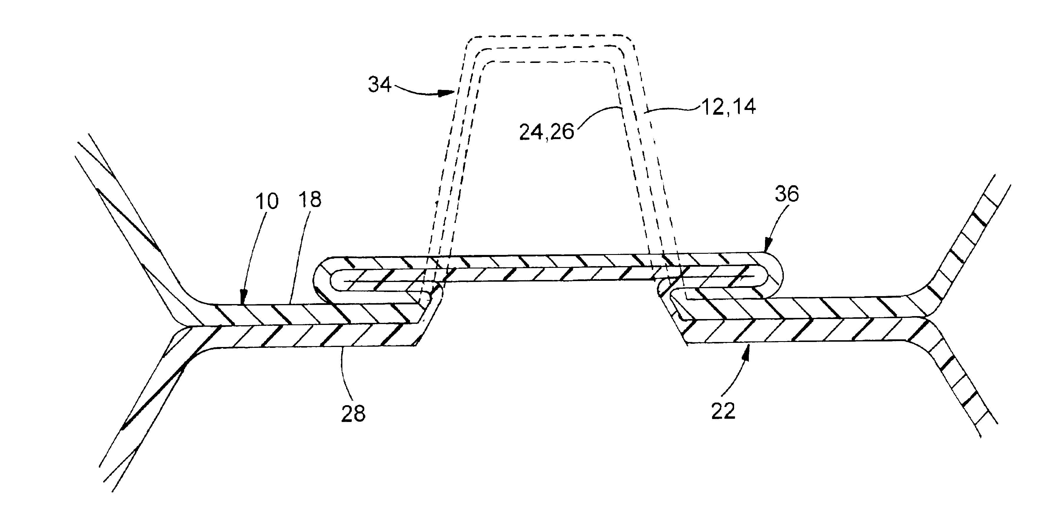
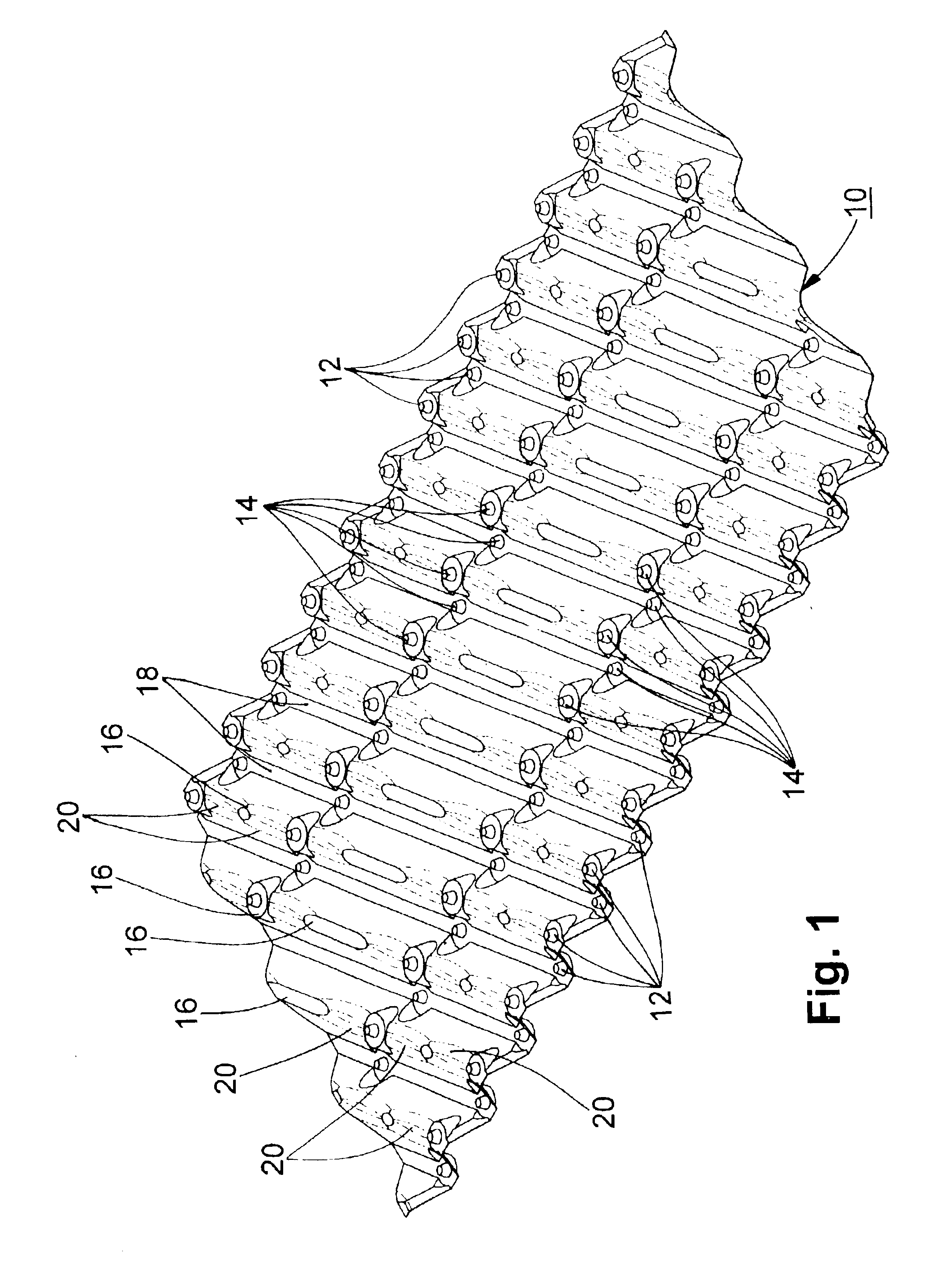
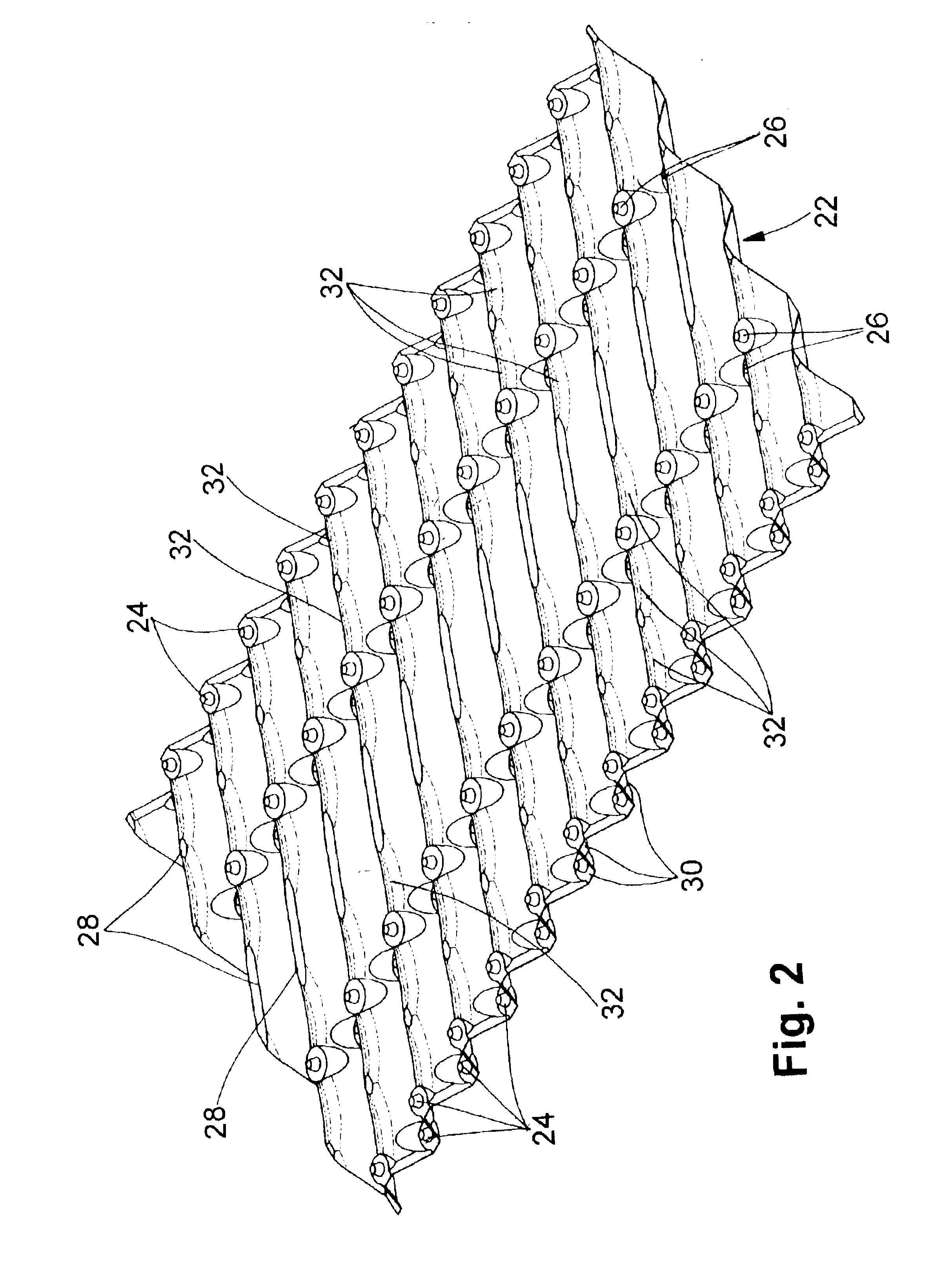
Contact sheets that can be used in accordance with the present invention can be of any type, so long as at least two of the contact sheets have a projection extending out from one surface of the sheet, each projection defining a corresponding depre...


PUM

PropertyMeasurementUnit
shapeaaaaaaaaaa
heataaaaaaaaaa
wettabilityaaaaaaaaaa

Abstract

A method of connecting contact sheets to form a contact body that provides for mechanically deforming at least same of both interior and edge projection-depression couplings formed in two sheets to form positive locks in a pair of sheets, and then mechanically deforming only edge projections to form positive locks between at least two pairs of sheets, thereby forming the contact body.

Description

BACKGROUND OF THE INVENTIONThe present invention relates to contact bodies, such as gas / liquid contact bodies, comprised of two or more individual contact sheets, and to a method and apparatus for connecting two or more contact sheets. More particularly, the present invention relates to a method and apparatus for connecting two or more contact sheets with at least one positive lock between the contact sheets, and to the contact bodies so made.Various types of apparatus and products are known in the art for providing gas / liquid contact for several different purposes. Among such purposes, for example, are heat transfer, such as evaporative heat exchangers, the removal of pollutants from a gas (gas scrubbing), use in trickle filters (a type of biological filter), artificial reefs, and other industrial or other types of uses. Gas / liquid contact bodies are generally designed to promote the intimate mixture of and heat exchange between two fluid streams. The fluid streams can be concurren...

Claims


Application Information

Patent Timeline
Patent Type & Authority Patents(United States)
IPC IPC(8): B01J19/32B21D39/03B29C65/00B29C65/56B29C65/60F28F25/00F28F25/08F28F25/06B21D39/02B21D53/04
CPCB01J19/32B21D39/031B29C65/607B29C66/21B29C66/438B29C66/83513F28F25/087B29C66/1312Y10T428/24694B01J2219/32213B01J2219/32241B01J2219/32248B01J2219/32255B01J2219/32275B01J2219/32279B01J2219/32282B01J2219/32408B01J2219/32416B01J2219/32483B01J2219/328B01J2219/3282B01J2219/3284B01J2219/3288B01J2219/33B29K2023/06B29K2023/12B29K2025/00B29K2027/00B29K2027/06B29K2055/02B29K2059/00B29K2069/00B29K2071/00B29K2071/12B29K2077/00B29K2081/04B29K2081/06B29L2024/00B29L2031/18B01J2219/3221Y10T29/49936Y10T428/24702Y10T428/24669Y10T29/53422Y10T428/24322Y10T29/49943Y10T428/24711Y10T428/24628Y10T428/24273B29C66/43B29C65/00B29C66/54B29C66/71B29C66/721B29C66/73921B29K2083/00B29K2067/00B29K2063/00B29K2027/16B29K2027/08B29K2025/08B29K2025/06F28F25/08
Inventor AULL, RICHARD J.BINO, ALKRELL, TIMOTHY E.RYE, PALLETRUEX, ANDREW L.
Owner BRENTWOOD INDS
Why Eureka
Try Eureka