Cable-type steering device with variable steering gear ratio

a technology of steering gear ratio and cable type, which is applied in the direction of gearing, mechanical equipment, transportation and packaging, etc., can solve the problem that the steering characteristic cannot be made variable, and achieve the effect of suppressing the change in the steering gear ratio and reducing the load acting

Inactive Publication Date: 2005-04-12
HONDA MOTOR CO LTD
View PDF10 Cites 6 Cited by
  • Summary
  • Abstract
  • Description
  • Claims
  • Application Information

AI Technical Summary

Benefits of technology

With the above arrangement, the actuator is driven in accordance with the steering torque input to the steering wheel, and hence the assisting torque of the actuator can be input to the steering gear box to decrease the load acting on the operating cables, thereby suppressing change in the steering gear ratio due to the elongation of the operating cables.

Problems solved by technology

As a result, the steering characteristic cannot be made variable, e.g., from sensitive to obtuse, in accordance with the position of the steering wheel.

Method used


Image

  • Cable-type steering device with variable steering gear ratio
  • Cable-type steering device with variable steering gear ratio
  • Cable-type steering device with variable steering gear ratio

Examples


first embodiment

FIGS. 1 to 8 show the present invention.

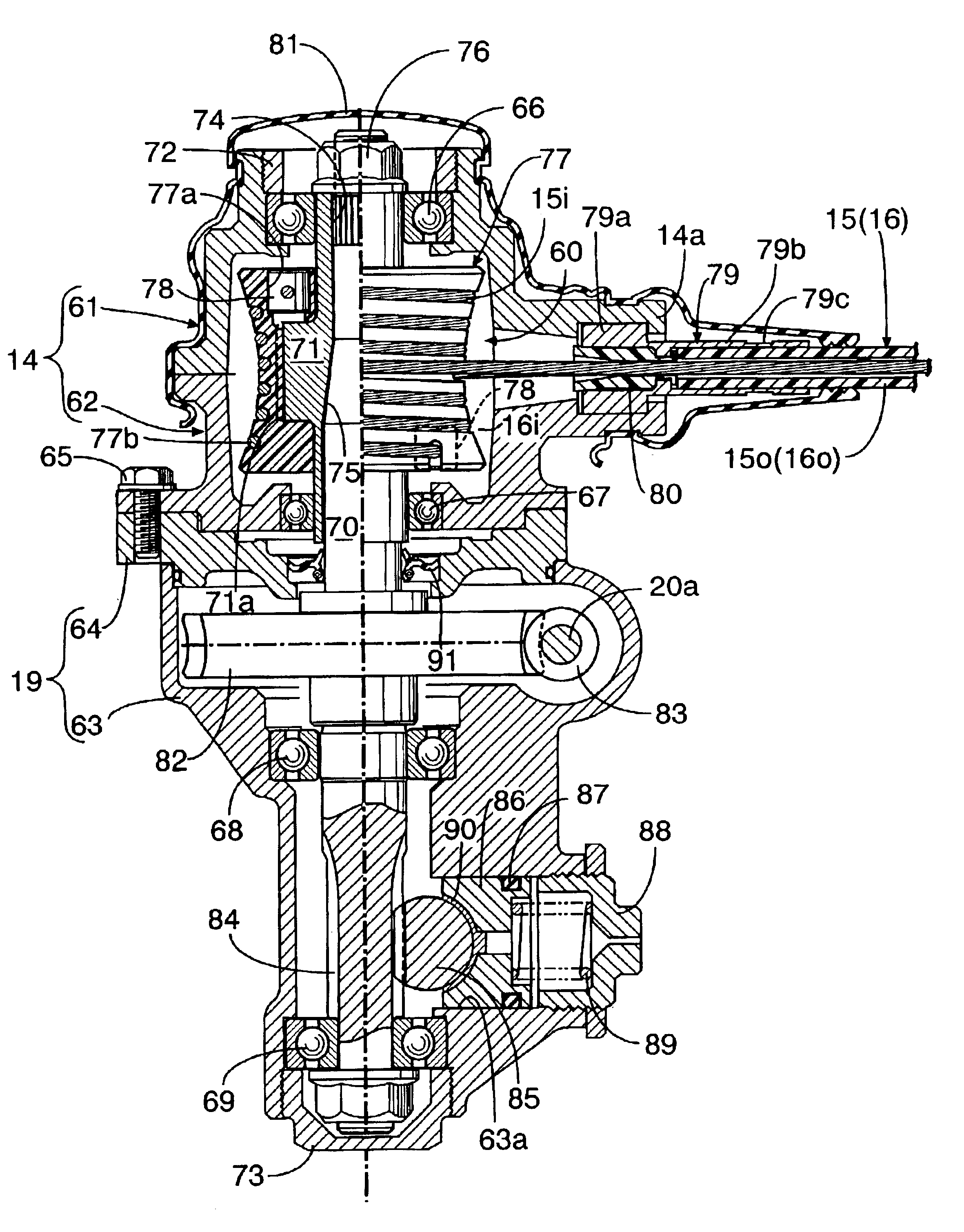
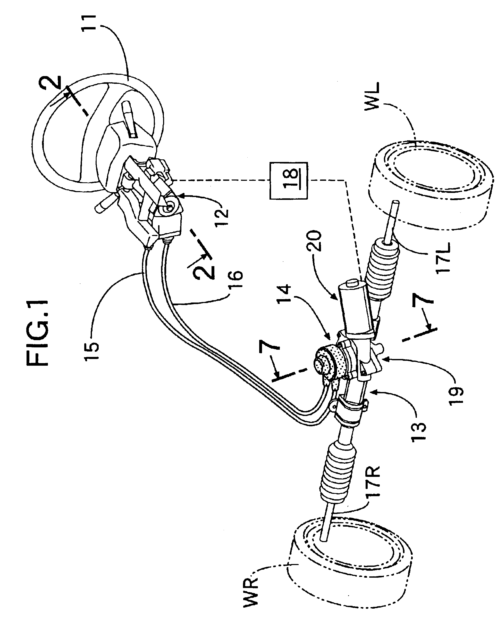
As shown in FIG. 1, a driving pulley casing 12 mounted in front of a steering wheel 11 of an automobile and a follower pulley casing 14 mounted above a steering gear box 13, are connected to each other by two operating cables 15 and 16 each comprising a Bowden cable. Tie rods 17L and 17R extending in a lateral direction of a vehicle body from opposite ends of the steering gear box 13 are connected to knuckles (not shown) which support left and right wheels WL and WR. A steering torque sensor for detecting a steering torque input to the steering wheel 11 is accommodated in the driving pulley casing 12. An actuator 20 mounted on a gear casing 19 integral with the follower pulley casing 14 is operated by a command from a control unit 18 to which a detected steering torque is input, thereby assisting the steering operation conducted by a driver.

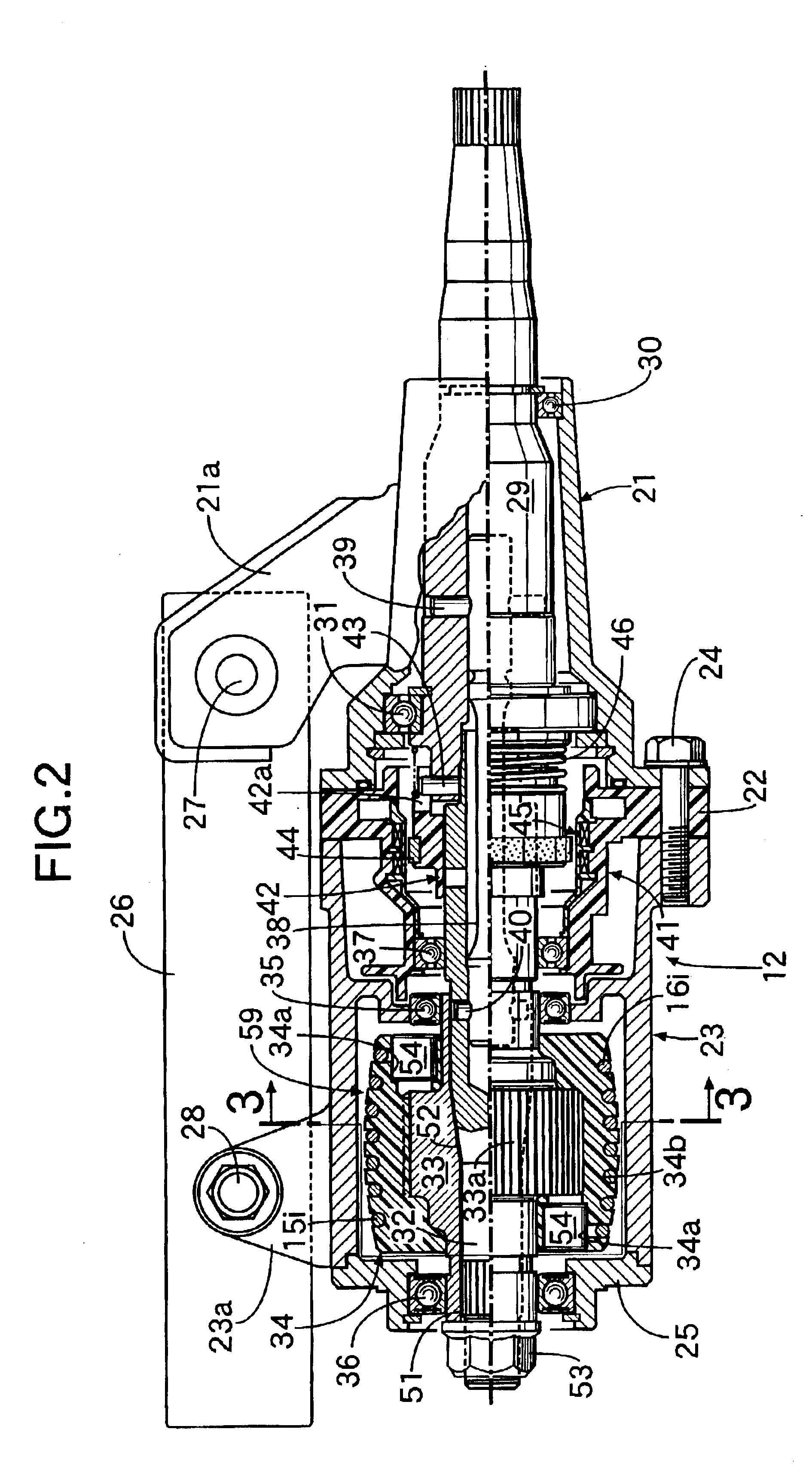
As shown in FIG. 2, the driving pulley casing 12 comprises a rear housing 21, a center housing 22 and a ...

second embodiment

the present invention will now be described with reference to FIGS. 9 to 11.

In the second embodiment, the shapes of a driving pulley 59 and a follower pulley 60 are different or reversed from those in the first embodiment, and the other structures are the same as in the first embodiment.

The generatrix of the follower pulley 60 in the second embodiment is bulged outwards at an axially central portion and parallel to the rotary shaft at axially opposite ends, and the generatrix of the driving pulley 59 is depressed inwards at an axially central portion and parallel to the rotary shaft at axially opposite ends. That is, both the generatrices have complementary shapes. As a result, a steering gear ratio characteristic shown in FIG. 11 is such that when the steering wheel 11 is in the vicinity of the neutral position, the steering ratio is larger, so that the steering characteristic becomes obtuse, and when the steering wheel 11 is in the vicinity of the end position, the steering ratio ...


PUM


Abstract

A cable-type steering device in which the steering gear ratio can be varied in accordance with the position of a steering wheel comprises operating cables wound around an outer peripheral surface of a driving pulley rotatably connected to a steering wheel and an outer peripheral surface of a follower pulley rotatably connected to a steering gear box for steering wheels so that a steering torque input to the steering wheel is transmitted through the operating cables to the steering gear box. The driving pulley is of a barrel-shape with the diameter being larger at an axially central portion and smaller at axially opposite ends. The follower pulley is of a bobbin-shape or sand-clock-shape with the diameter being smaller at an axially central portion and larger at axially opposite ends. Thus, the steering gear ratio (a ratio of the steering angle of the steering wheel / a transmitted steering angle for the wheels) can be varied in accordance with the position of the steering wheel.

Description

BACKGROUND OF THE INVENTION1. Field of the InventionThe present invention relates to a cable-type steering device in which a steering wheel and a steering gear box are connected to each other by a flexible operating cable such as a Borden cable, and particularly to such a device with a variable steering gear ratio.2. Discussion of Relevant ArtConventional cable-type steering devices are known, for example, from Japanese Patent Application Laid-open Nos. 2000-25623, 10-59197 and 8-2431.A driving pulley and a follower pulley in the conventional cable-type steering device are of the same columnar shape, and two operating cables are wound around grooves defined helically in outer peripheral surfaces of these pulleys. When a steering wheel is operated, one of the operating cables is wound around the driving pulley and drawn out of the follower pulley, and the other cable is drawn out of the driving pulley and wound around the follower pulley, whereby the rotation of the driving pulley is...

Claims


Application Information

Patent Timeline
Patent Type & Authority Patents(United States)
IPC IPC(8): B62D6/10B62D6/08B62D1/16F16H19/00B62D5/04
CPCB62D1/163F16H19/0659B62D6/10
Inventor SHIMIZU, YASUO
Owner HONDA MOTOR CO LTD
Why Eureka
Try Eureka