Corrugated tube fitting

a technology of corrugated tubing and fittings, which is applied in the direction of hose connections, fluid pressure sealing joints, sleeve/socket joints, etc., can solve the problems of increasing complexity of known fittings, reducing mechanical strength and sealing performance, and reducing the cost of installation. the effect of complexity or expens

Inactive Publication Date: 2005-04-12
HIGHLANDS CORP
View PDF19 Cites 58 Cited by
  • Summary
  • Abstract
  • Description
  • Claims
  • Application Information

AI Technical Summary

Benefits of technology

It is an object of the invention to provide a fitting for use in various forms of corrugated tubing terminations and couplings, having improved mechanical strength and sealing performance compared to known fitting, without adding to complexity or expense.
Another object is to provide a fitting that can be retightened, reassembled and / or re-used, without undue loss of sealing effectiveness.
It is a further object to produce a metal / metal sealing junction at a narrow sealing line between relatively incompressible metal structures that clamp onto and deform the cut end of a length of corrugated tubing, in a way that provides sealing and mechanical attachment strength due to the shape to which the tubing is deformed.

Problems solved by technology

However, couplings made at the ends of lengths of corrugated tubing are somewhat of a challenge.
The known fittings have a range of complexity.
However, the cut end of the tubing may not be cut exactly on a plane perpendicular to the axis of the tube.
The cut edge may have irregularities from the cutting tool.
These variations complicate the possibility of a direct endwise seal between the cut end and an abutting surface arranged substantially in a plane normal to the axis of the tube.
Forming a flat flange reduces the effect of the cut end not being precisely formed.
However a wide flat area of contact between a flange and a corresponding flat annulus may not provide a highly effective metal / metal seal, or a distinct edge to bear against a compressible gasket material.
Metal-to-metal seals are strong but comprise material with comparatively little ability to recover their shape after deformation.
It is possible to provide spring-like metal that has resilience, but it is generally not compressible in a way that facilitates sealing along a distinct sealing surface or edge.
The metal material has advantages of structural strength, and disadvantages as to compliance for sealing.
A more malleable metal is possible to conform under pressure, but is permanently deformed and lacks compliance under changing conditions.

Method used


Image

  • Corrugated tube fitting
  • Corrugated tube fitting
  • Corrugated tube fitting

Examples


Embodiment Construction

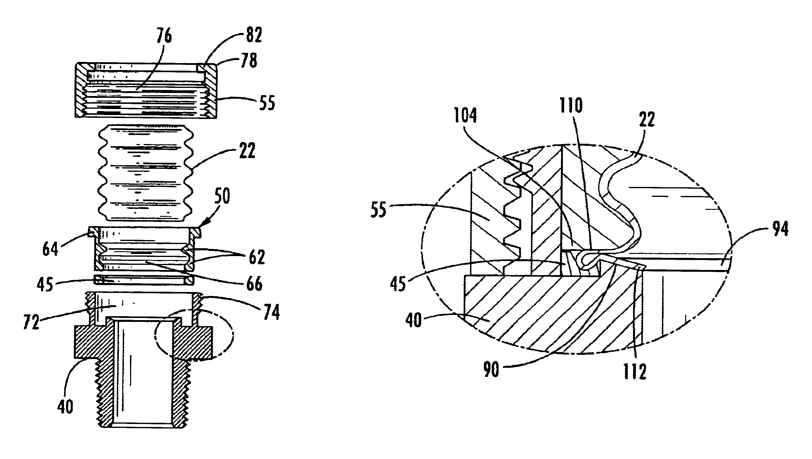
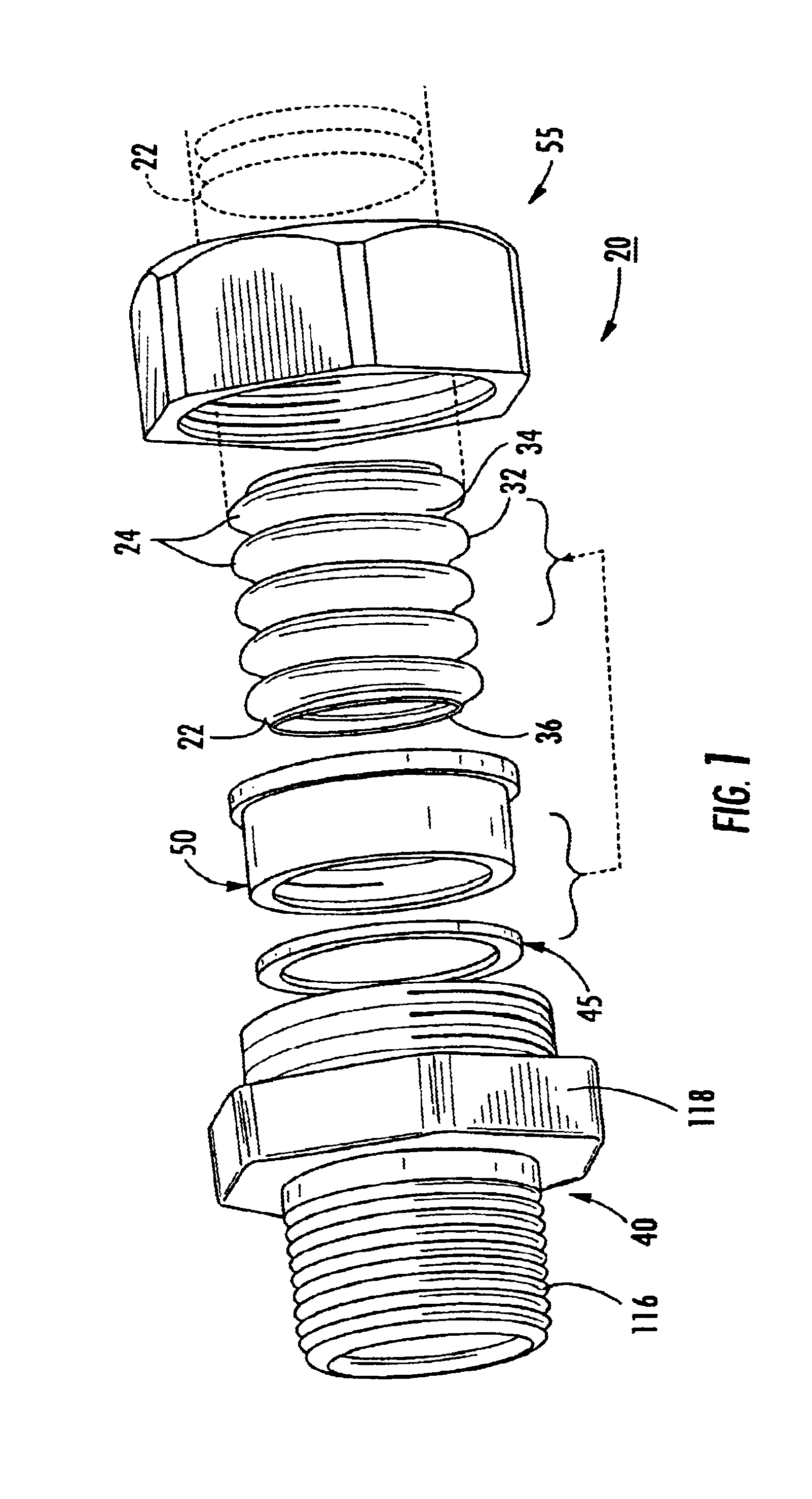
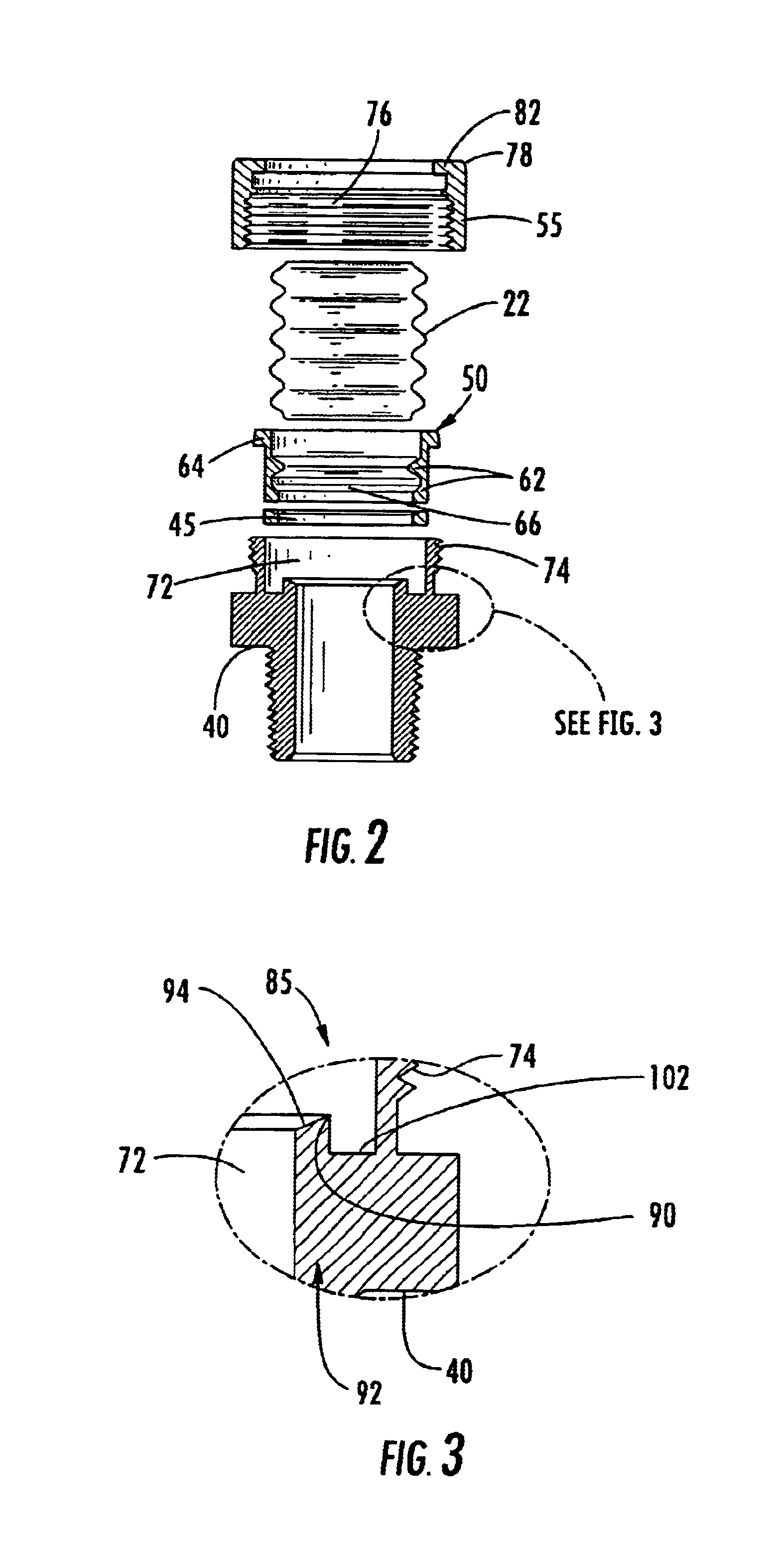
An inventive fitting 20 for an end of a length of tubing 22 such as corrugated stainless steel tubing is shown in FIGS. 1-6. FIG. 1 shows the respective parts in an exploded view along the end of a length of tubing of indefinite length, to be terminated by the fitting 20. The termination can be for any purpose that benefits from a sealed connection to the tubing, the illustrated example being a union fitting between the tubing and a pipe thread provided on a generally cylindrical fitting body having wrench flats, as typically used for making a union with a rigid pipe. The invention is equally applicable to sealed connections with other particular body elements such as couplings between lengths of tubing of the same or different structure, hookups with valves and regulators, reservoir and vessel walls, joints such as tees and elbows, manifolds, bulkheads, etc.

The tubing 22 has corrugations 24 or periodic variations ranging between a maximum diameter 32 and a minimum diameter 34, spac...


PUM


Abstract

A fitting for an end of a length of corrugated tubing has a split retainer that grips the tubing corrugations, and is engaged between a fitting body and a nut. Upon tightening the nut on the fitting body, the endmost corrugation is compressed between the retainer and a sealing seat on the fitting body arranged to provide a narrow metal-metal sealing junction and also a gasket seal. The fitting body has an inwardly tapered conical surface with a circular outer radius surrounded by an annular groove, thus forming a sealing edge, and the annular groove carries a gasket. The conical surface is dimensioned so that the sealing edge falls between the maximum and minimum diameters of the endmost corrugation. As the fitting is tightened, the endmost corrugation is collapsed between the sealing edge and the retainer, providing a metal / metal clamped sealing junction. The outer diameter part of the endmost corrugation is wrapped into a bead or torus that compresses the gasket, forming a metal / gasket additional seal.

Description

BACKGROUND OF THE INVENTION1. Field of the InventionThe invention concerns a fitting for sealed termination of a length of corrugated tubing, especially corrugated stainless steel tubing, for example as used for gaseous fuel lines.The fitting includes a threaded fitting body and nut, cooperating with a retainer having one or more split rings that grip the corrugations adjacent to an end of the tubing. The tubing preferably is cut near a minimum diameter between corrugations and the retainer is placed axially behind the endmost corrugation. The nut and fitting body are placed on axially opposite sides of the retainer near the cut end. Tightening the nut on the fitting body forces the cut end of the tube axially against the fitting body, which has a dual sealing structure for providing a thin circular metal / metal sealing junction and an adjacent metal / gasket sealing junction.More particularly, an inwardly tapering conical surface of the fitting body has a sharply formed outer edge. Th...

Claims


Application Information

Patent Timeline
Patent Type & Authority Patents(United States)
IPC IPC(8): F16L25/00
CPCF16L25/0036Y10S285/903
Inventor EDLER, DAVID
Owner HIGHLANDS CORP
Why Eureka
Try Eureka