
Damping sleeve with resilient support members

a support member and resilient technology, applied in the field of sleeves, can solve the problems of pernicious sources of unwanted noise, pernicious wiring harnesses, annoying and a cause of concern for vehicle occupants

Inactive Publication Date: 2005-04-12
FEDERAL MOGUL WORLD WIDE
View PDF40 Cites 15 Cited by
  • Summary
  • Abstract
  • Description
  • Claims
  • Application Information

AI Technical Summary

Benefits of technology

It is an object of the invention to provide a sleeve for protecting elongate substrates from vibration.
It is yet another object of the invention to provide a protective sleeve which is flexible and resilient and able to conform to a curved shape or path to follow the path of a substrate.

Problems solved by technology

In automotive applications, wiring harnesses in particular are pernicious sources of unwanted “rattle noise” due to their propensity to resonate in response to structure borne vibration caused by engine operation or irregularities of the road surface over which the vehicle is passing.
Although the harness is intermittently attached to the vehicle structure, the lengths of the harness between attachment points will often resonate and rattle against the structure in response to relatively low-frequency vibrations within the range of human hearing and provide a source of noise, which is both annoying and a cause of concern to the vehicle occupants.
Aside from the noise annoyance, vibration of wiring harnesses will cause fatigue failures of the wiring, solder joints or mechanical connectors, leading to electrical malfunctions, such as short circuits, which could result in a vehicle fire.
The failure due to vibration and fatigue of other elongate substrates, such as fuel lines or brake lines, also has catastrophic potential.

Method used


Image

  • Damping sleeve with resilient support members
  • Damping sleeve with resilient support members
  • Damping sleeve with resilient support members

Examples


Embodiment Construction

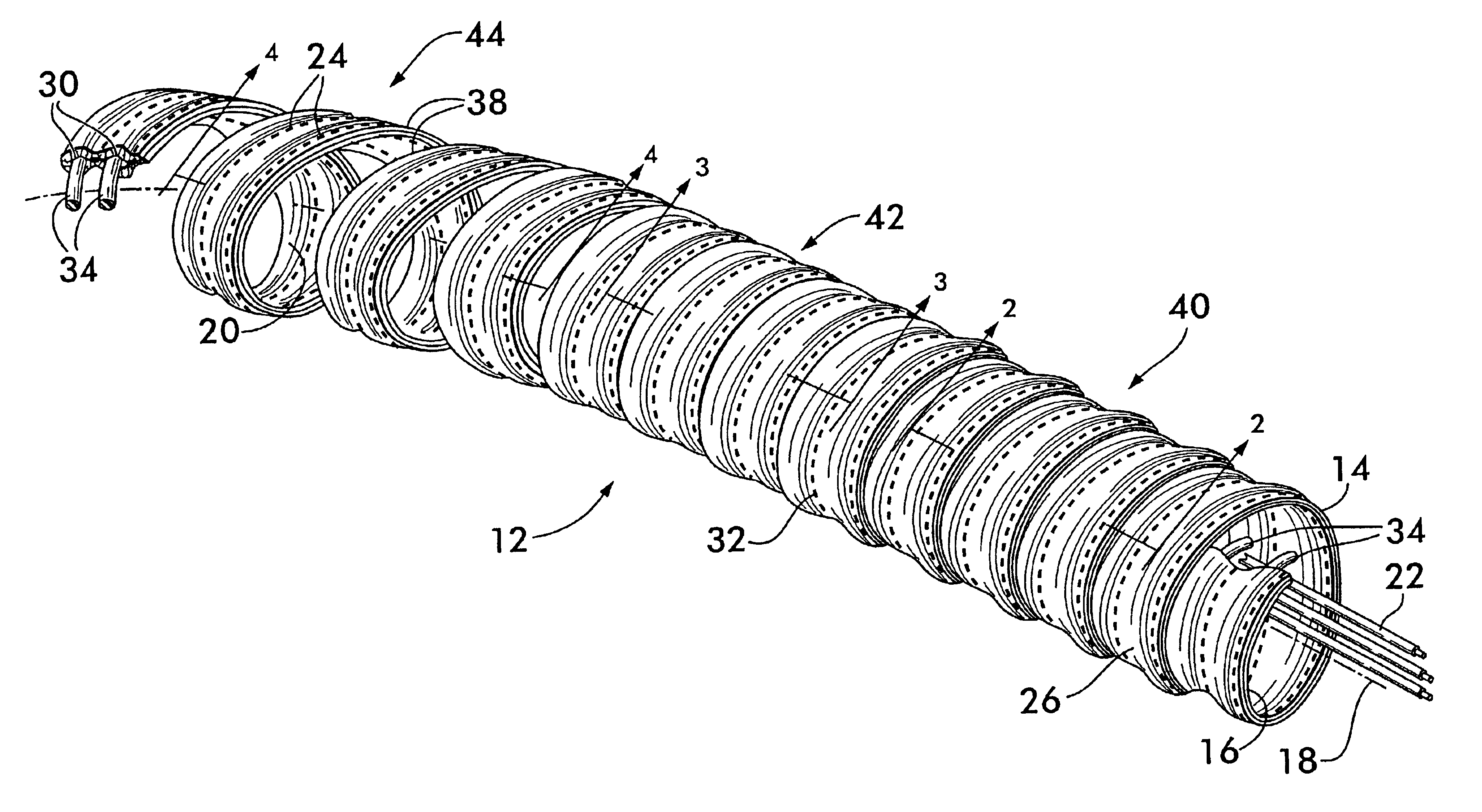
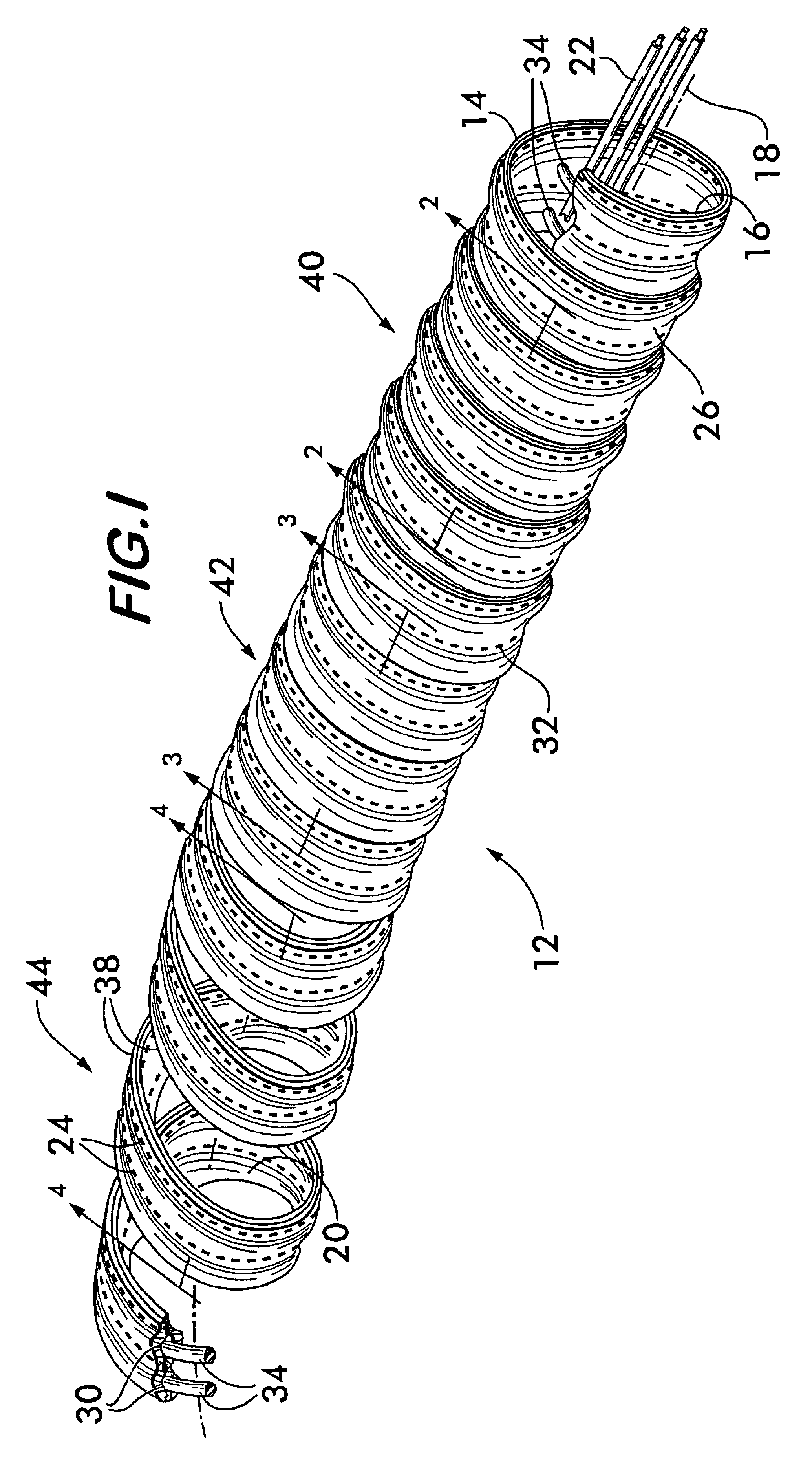
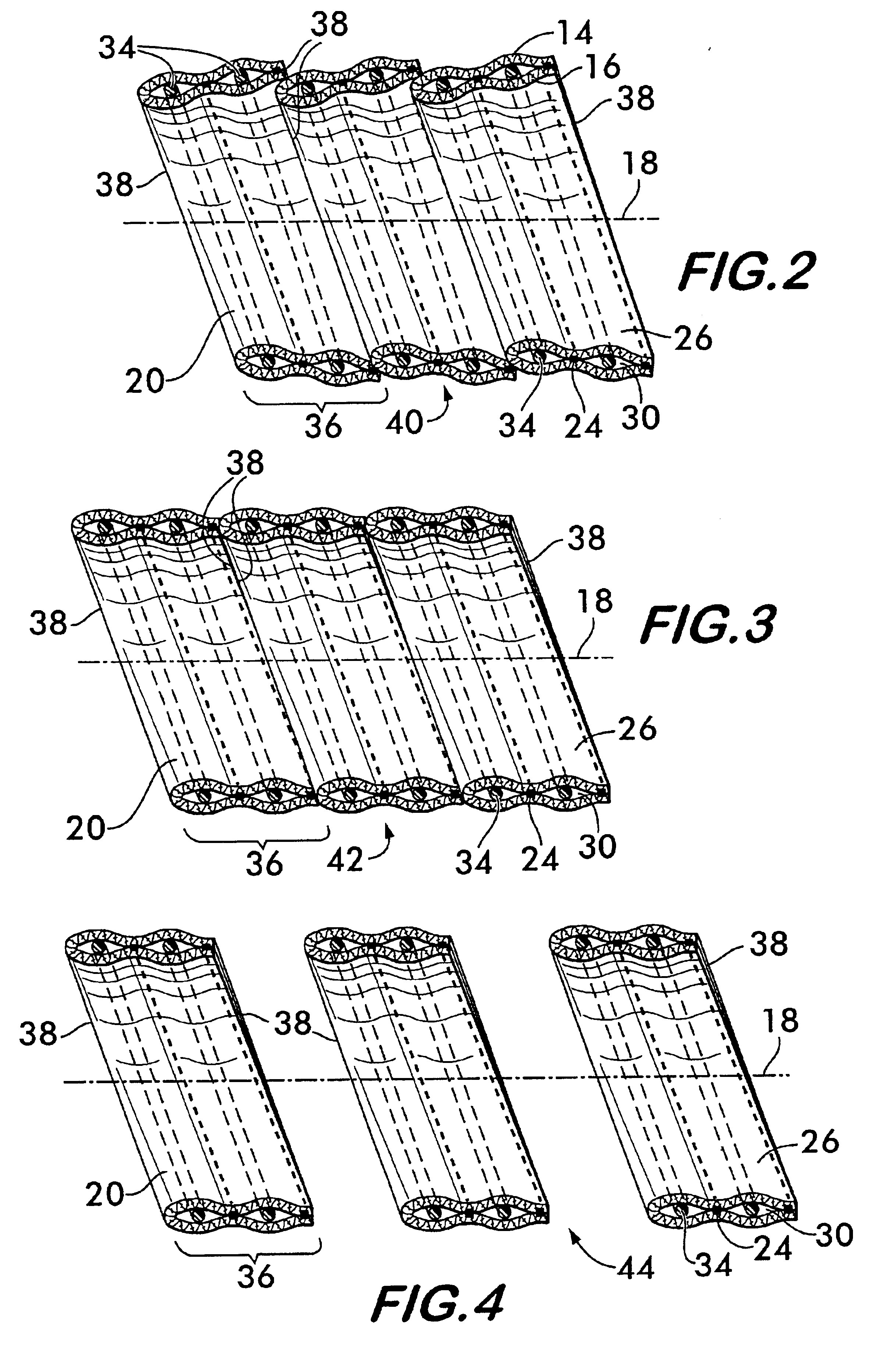
FIG. 1 shows a damped sleeve 12 formed from a flexible damping layer 14 and a flexible backing layer 16. Preferably, the damping layer forms the outwardly facing surface of sleeve 12 and comprises an energy absorbing material, such as a non-woven felt. Synthetic polymers such as polyester, polypropylene and nylon felts are preferred for their robustness, low cost and ready availability, but felts made from organic fibers are also feasible. Felts are preferred because the random fiber structure provides for effective absorption of vibrational energy, thereby providing effective damping of acoustic noise and structure borne vibration.

The damping layer 14 and the backing layer 16 are positioned coaxially around an axis 18, the layers being spaced radially outwardly from the axis and defining a central space 20 adapted to receive elongated substrates 22, which may be, for example, a wiring harness. The damping layer 14 and the backing layer 16 are joined together by a plurality of lines...


PUM

PropertyMeasurementUnit
flexibleaaaaaaaaaa
dampingaaaaaaaaaa
widthaaaaaaaaaa

Abstract

A damped sleeve having a damping layer attached to a backing layer is disclosed. The damping layer is formed from a non-woven energy absorbing felt and is attached to the backing layer by lines of attachment which define pockets between the layers. The layers are positioned coaxially around an axis and define a central space for receiving elongated items to be protected from vibration. Resilient filamentary support members are arranged between the damping and backing layers to support the layers radially in spaced relation relative to the axis. The support members may be helically wrapped around the axis, circumferentially positioned or arranged in a zig-zag pattern transversely to the axis. A slit in the layers provides access to the central space.

Description

FIELD OF THE INVENTIONThis invention concerns sleeving for encasing and protecting elongated substrates, such as wiring harnesses, and for reducing rattle noise from such substrates when they are used in a high-vibration environment.BACKGROUND OF THE INVENTIONElongated substrates, such as wiring harnesses, fluid conduits, such as brake lines and fuel lines, and optical fiber bundles are often used in automotive, aerospace and marine environments where they are subjected to significant ambient vibration. In automotive applications, wiring harnesses in particular are pernicious sources of unwanted “rattle noise” due to their propensity to resonate in response to structure borne vibration caused by engine operation or irregularities of the road surface over which the vehicle is passing. Wiring harnesses typically extend substantially throughout the vehicle's passenger compartment where they distribute power and control signals from the engine compartment to the dashboard instruments, i...

Claims


Application Information

Patent Timeline
Patent Type & Authority Patents(United States)
IPC IPC(8): H02G3/04B60R16/02F16L3/26F16L57/00
CPCF16L3/26H02G3/0468F16L57/00Y10T156/1002Y10T428/249953Y10T428/249958Y10T428/249986H02G3/04
Inventor FRYBERGER, JR., SAMUEL B.SNYDER, BRIAN M.
Owner FEDERAL MOGUL WORLD WIDE
Learn More