

Light-emitting diode with plastic reflector cup
a technology of light-emitting diodes and reflector cups, which is applied in the direction of basic electric elements, electrical equipment, semiconductor devices, etc., can solve the problems that the oxidation of metal reflectors cannot be completely prevented, and achieve the effects of improving the reflectivity of the surface, improving the light output of the light-emitting diodes, and convenient manufacturing
- Summary
- Abstract
- Description
- Claims
- Application Information
AI Technical Summary
Benefits of technology
Problems solved by technology
Method used
Image

Examples
first embodiment
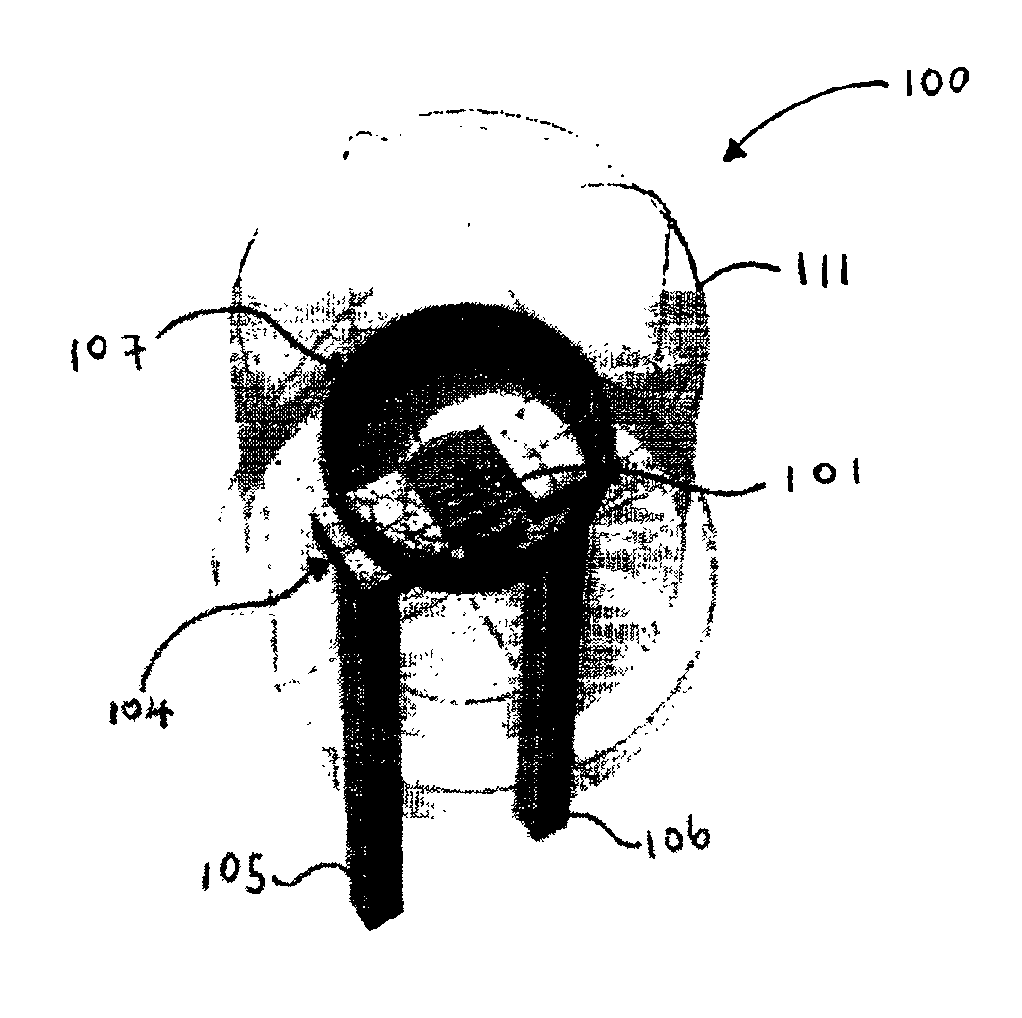
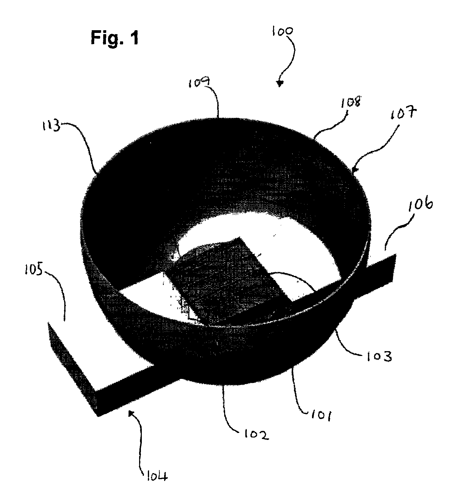
FIG. 1 shows a partial perspective view of a light-emitting diode 100 according to the present invention.
The light-emitting diode 100 of FIG. 1 comprises a light-emitting diode die 101 for emitting light and having a positive terminal 102 and a negative terminal 103. Further, the light-emitting diode 100 comprises a lead frame 104 comprising a positive lead frame portion 105 and a negative lead frame portion 106. The positive lead frame portion 105 is electrically coupled to the positive terminal 102. The negative lead frame portion 106 is electrically coupled to the negative terminal 103. Further, the light-emitting diode 100 comprises a reflector cup 107 comprising a body 108 having an inner surface 109 facing the light-emitting diode die 101 and an outer surface 110 facing outwards from the light-emitting diode die 101. The reflector cup 107 is arranged to reflect light emitted from the light-emitting diode die 101 away from the light-emitting diode die 101. The body 108 of the r...
second embodiment
FIG. 4 shows a partially exploded partial perspective view of a light-emitting diode 100 according to the present invention.
In this second embodiment of the invention, the light-emitting diode 100 further comprises an inner frame 401 comprising a positive inner frame portion 402 and a negative inner frame portion 403. The positive inner frame portion 402 is electrically coupled between the positive terminal 102 and the positive lead frame portion 105, and the negative inner frame portion 403 is electrically coupled between the negative terminal 103 and the negative lead frame portion 106. The positive inner frame portion 402 comprises a positive locking member 404, by means of which the positive inner frame portion 402 is clamped to the positive lead frame portion 105 so as to generate a mechanical and electrical connection between the positive inner frame portion 402 and the positive lead frame portion 105. The negative inner frame portion 403 comprises a negative locking member 40...
third embodiment
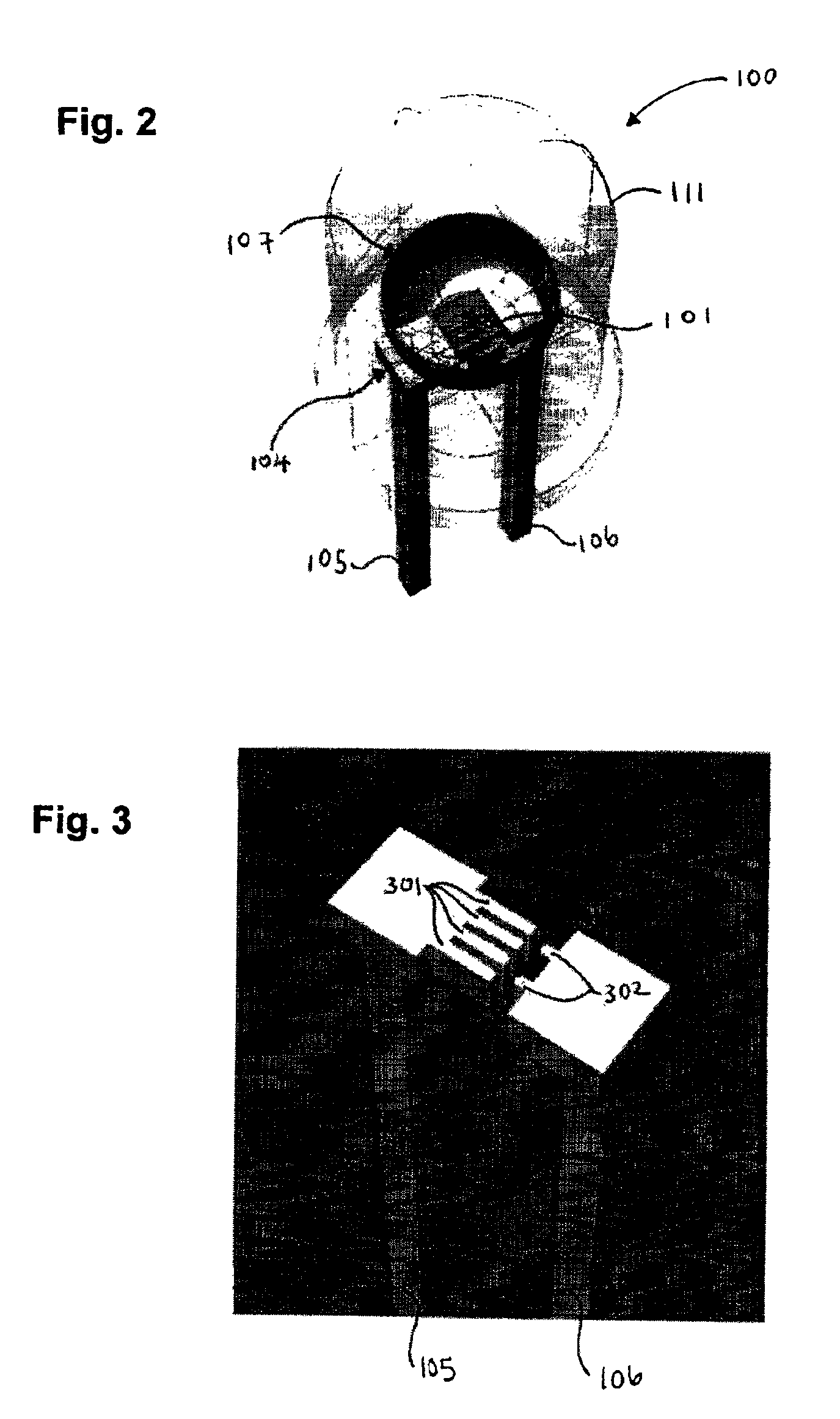
FIG. 7 shows a perspective view of a light-emitting diode 100 according to the present invention.
In this third embodiment of the present invention, the positive lead frame portion 105 and the negative lead frame portion 106 extend in a direction extending generally perpendicular with respect to a direction of strongest emission of the light-emitting diode die 101.
FIG. 8 shows a side view of a light-emitting diode 100 according to a fourth embodiment of the present invention. In this fourth embodiment of the present invention, the light-emitting diode die 101 is mounted on a printed circuit board 901.
FIG. 9 shows a top perspective view of the light-emitting diode 100 of FIG. 8. The light-emitting diode die 101 is mounted on the printed circuit board 901. The printed circuit board 901 comprises a plurality of contact fingers 301, 302 printed thereon, wherein the structure of the contact fingers 301, 302 is designed to match the structure of the terminals 102, 103 of the light-emitting...
PUM
 Abstract
Description
Claims
Application Information