Flexible circuit board for mounting light emitting element, illumination apparatus, and vehicle lighting apparatus

a flexible circuit board and light emitting element technology, applied in semiconductor devices for light sources, printed circuit non-printed electric components association, lighting and heating apparatus, etc., can solve the problems of difficult to reduce the price of flexible circuit boards, resin compositions as described above are expensive, etc., to achieve higher thermal conductivity, increase the yield of products, and the effect of increasing the yield

Active Publication Date: 2014-01-23
CANON COMPONENTS INC
View PDF3 Cites 4 Cited by
  • Summary
  • Abstract
  • Description
  • Claims
  • Application Information

AI Technical Summary

Benefits of technology

The present invention provides a flexible circuit board that can prevent an increase in temperature of the light emitting element by radiating the heat generated by the light emitting element. It has a high surface reflectance to efficiently use the emitted light. The flexible circuit board incorporates a metal substrate that suppresses deformation and dimensional change caused by temperature changes or moisture absorption, resulting in an increased yield of products. Aluminum has higher thermal conductivity and thermal dissipation capability than a resin composition, reducing thermal load on the component or device to be mounted. It also blocks electromagnetic waves and prevents unwanted emissions (EMI) from affecting external components or devices. The price of the base film is lower than a resin composition, reducing product price.

Problems solved by technology

However, a configuration using a film of a resin composition as a base film of a flexible circuit board may suffer from the problems below.
Resin compositions as described above are expensive, which makes it difficult to reduce the price of a flexible circuit board.
A process of forming an opening in a base film of a resin composition by etching is costly and is very low in processing rate.
Die-punching requires facilities for punching, which increases facilities cost.
However, a base film made of a resin composition is considerably deformed or varies widely in dimensions due to a temperature change, moisture absorption, or the like.
However, due to the low thermal conductivity of a resin composition, the higher density or the larger number of layers increases thermal load on a mounted device and the like.
An increase in the density or the number of layers is thus hard to achieve.
The flexible circuit board configured as described above may pose the following problems when used as a substrate for mounting a light emitting element, such as a light emitting diode (LED).
In general, resin materials have low thermal conductivities, so that the flexible circuit board, whose base film and cover film are made of a resin material, may be unable to sufficiently radiate the heat generated by the LED.
However, polyimide, which is used as the material of the base film and the cover film, is brown in color and therefore tends to absorb the light emitted by the LED, thereby reducing the amount of light available.
However, the arrangement in which the radiator plate is mounted on the back surface leads to an increase in cost.
Furthermore, none of the prior-art documents described above discloses an arrangement that achieves both radiation of the heat generated by the LED and efficient use of the light emitted by the LED.Patent Document 1: Japanese Laid-open Patent Publication No. 05-029395Patent Document 2: Japanese Laid-open Patent Publication No. 2007-18926Patent Document 3: Japanese Laid-Open Patent Publication No. 2009-25679Patent Document 4: Japanese Laid-Open Patent Publication No. 2007-110010Patent Document 5: Japanese Laid-Open Patent Publication No. 2009-302110Patent Document 6: Japanese Laid-Open Patent Publication No. 2010-232252

Method used


Image

  • Flexible circuit board for mounting light emitting element, illumination apparatus, and vehicle lighting apparatus
  • Flexible circuit board for mounting light emitting element, illumination apparatus, and vehicle lighting apparatus
  • Flexible circuit board for mounting light emitting element, illumination apparatus, and vehicle lighting apparatus

Examples


first embodiment

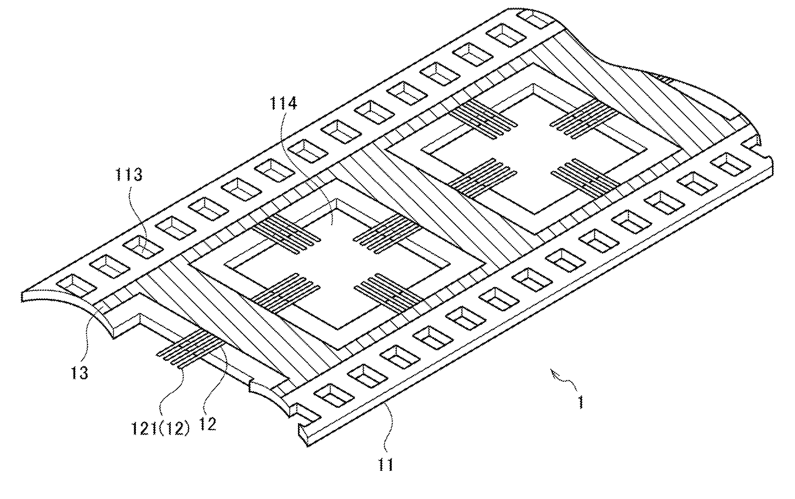
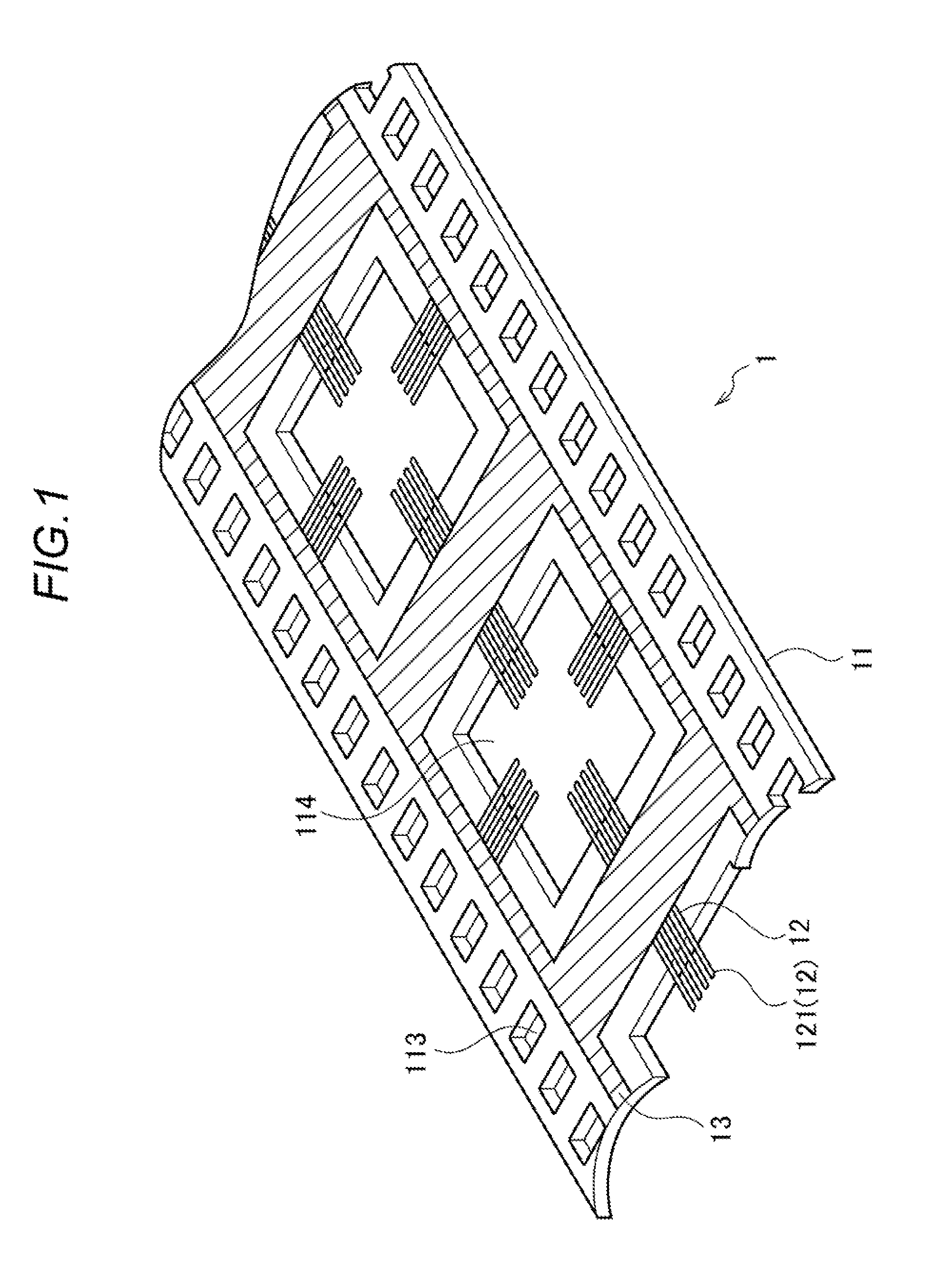
[0085]An first embodiment of the present invention will be described below in detail with reference to the drawings. A flexible circuit board 1 according to the first embodiment of the present invention is a suitable flexible circuit board (FPC: Flexible Print Circuit) for a carrier tape for TAB (Tape Automated Bonding).

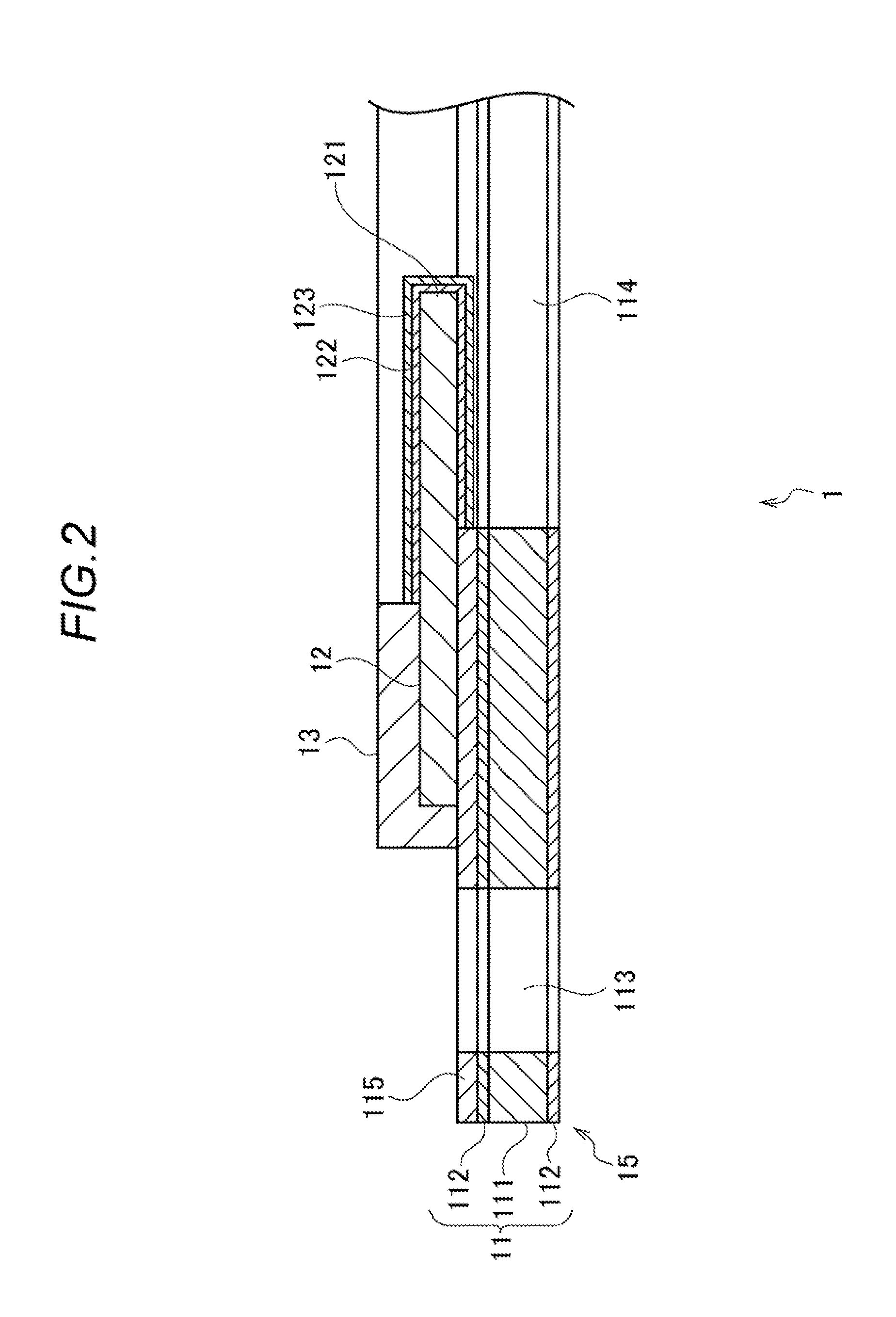
[0086]The configuration of the flexible circuit board 1 according to the first embodiment of the present invention will first be described. FIG. 1 is an external perspective view schematically showing the configuration of the flexible circuit board 1 according to the first embodiment of the present invention. FIG. 2 is a cross-sectional view schematically showing the configuration of the flexible circuit board 1 according to the first embodiment of the present invention.

[0087]As shown in FIGS. 1 and 2, the flexible circuit board 1 according to the first embodiment of the present invention includes a base film 11, a predetermined conductor pattern 12, and a second pro...

second embodiment

[0131]The flexible circuit board 3a for mounting a light emitting element according to a second embodiment of the present invention will be described with reference to FIGS. 9A and 9B. FIGS. 9A and 9B are schematic cross-sectional views showing configurations of the flexible circuit board 3a for mounting a light emitting element according to the second embodiment of the present invention. FIG. 9A shows a configuration in which the surface of a cover film 33a has no irregularities, and FIG. 9B shows a configuration in which the surface of the cover film 33a has irregularities.

[0132]As shown in FIGS. 9A and 9B, a base film 31a of the flexible circuit board 3a for mounting a light emitting element according to the second embodiment has a laminate structure comprising a film-shaped substrate 311 and protective films 312 formed on the surfaces of the substrate 311. The substrate 311 is made of a metal material. The substrate 311 is an aluminum film having a thickness of 8 to 100 μm, for ...

third embodiment

[0141]Next, the flexible circuit board 3b for mounting a light emitting element according to a third embodiment of the present invention will be described with reference to FIGS. 10A and 10B. The same components as those of the flexible circuit board 3a for mounting a light emitting element according to the second embodiment are denoted by the same reference numerals, and descriptions thereof may be omitted. FIGS. 10A and 10B are schematic cross-sectional views showing configurations of the flexible circuit board 3b for mounting a light emitting element according to the third embodiment of the present invention. FIG. 10A shows a configuration in which the surface of a reflecting film 36 has no irregularities, and FIG. 10B shows a configuration in which the surface of the reflecting film 36 has irregularities.

[0142]As shown in FIGS. 10A and 10B, a base film 31a, a wiring pattern 32, and a cover film 33a are the same as those of the flexible circuit board 3a for mounting a light emitt...


PUM


Abstract

A flexible circuit board 3a for mounting a light emitting element has base films 31a and 31b, a wiring pattern 32 formed on a surface of the base films 31a and 31b, and the cover films 33a and 33b that covers the base films 31a and 31b and the wiring pattern 32. At least one of the base film and the cover films 33a and 33b have a substrate 331 and 331a comprising a metal. The cover film 33a and 33b have such surface properties as to produce specular reflection or diffuse reflection of light or has substantially white reflecting films 36 and 333 on a surface of the cover film.

Description

CROSS-REFERENCE TO RELATED APPLICATIONS[0001]This is a continuation-in-part application of the U.S. application Ser. No. 13 / 351,323, filed on Jan. 17, 2012, and U.S. application Ser. No. 13 / 734,089, filed on Jan. 4, 2013.[0002]This application is based upon and claims the benefit of priority of the prior Japanese Patent Application No. 2011-007362, filed on Jan. 17, 2011, the Japanese Patent Application No. 2012-000748, filed on Jan. 5, 2012, and the Japanese Patent Application No. 2012-236025, filed on Oct. 25, 2012, the entire contents of which are incorporated herein by reference.BACKGROUND OF THE INVENTION[0003]1. Field of the Invention[0004]The present invention relates to a flexible circuit board for mounting a light emitting element, an illumination apparatus, and a vehicle lighting apparatus. In particular, the present invention relates to a flexible circuit board for mounting a light emitting element that allows radiation of heat generated by a light emitting element, such ...

Claims


Application Information

Patent Timeline
IPC IPC(8): H05K1/02H05K1/18
CPCH05K1/0277H05K1/181H05K1/056H05K1/189H05K3/4092H05K2203/1545F21Y2115/10F21V23/005H05K1/0274
Inventor UEHARA, HIROHARUNAKAI, KATSUHIDESHIRATO, HIROKI
Owner CANON COMPONENTS INC
Why Eureka
Try Eureka