Damper wire spring for a cathode ray tube

a cathode ray tube and wire spring technology, applied in the manufacture of electric discharge tubes, electrode systems, electric discharge tubes/lamps, etc., can solve the problems of visible display fluctuations, shadow mask vibration from external sources, etc., and achieve the effect of constant tension and reduction of vibration

Inactive Publication Date: 2005-04-12
THOMSON LICENSING SA
View PDF6 Cites 0 Cited by
  • Summary
  • Abstract
  • Description
  • Claims
  • Application Information

AI Technical Summary

Benefits of technology

The present invention provides an apparatus and method for retaining a damper wire used in a cathode ray tube to reduce vibration in a grill type mask assembly of a cathode ray tube. The damper wire is retained across a mask by a bimetal damper spring having a first end and an opposing second end. The second end is coupled to the frame of the grill type mask assembly. A tab located proximate the first end of the damper spring is adapted to accept the damper wire that traverses the mask. In an alternative embodiment, the damper wire is “tied” to the tab such that the spring maintains a constant tension on the damper wire.

Problems solved by technology

The shadow mask is subject to vibration from external sources (e.g., speakers near the tube).
Such vibration varies the positioning of the apertures through which the electron beam passes, resulting in visible display fluctuations.

Method used


Image

  • Damper wire spring for a cathode ray tube
  • Damper wire spring for a cathode ray tube
  • Damper wire spring for a cathode ray tube

Examples


Embodiment Construction

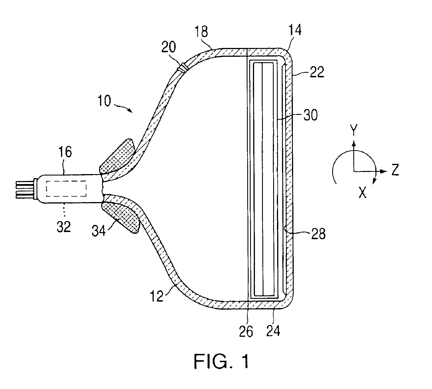
FIG. 1 shows a cathode ray tube 10 having a glass envelope 12 comprising a rectangular face plate panel 14 and a tubular neck 16 connected by a rectangular funnel 18. The funnel 18 has an internal conductive coating (not shown) that extends from an anode button 20 to a neck 16. The panel 14 comprises a viewing face plate 22 and a peripheral flange or sidewall 24 that is sealed to the funnel 18 by a glass frit 26. A three-color phosphor screen 28 is carried by the inner surface of the face plate 22. The screen 28 is a line screen with the phosphor lines arranged in triads, each triad including a phosphor line of each of the three colors. A grill type mask 30 is removably mounted in a predetermined spaced relation to the screen 28. An electron gun 32 (schematically shown by the dashed lines in FIG. 1) is centrally mounted within the neck 16 to generate three in-line electron beams, a center beam and two side beams, along convergent paths through the mask 30 to the screen 28.

The tube 1...


PUM


Abstract

An apparatus and method for retaining a damper wire used in a cathode ray tube to reduce vibration in the grill type mask assembly of a cathode ray tube. The damper wire is retained across a grill type mask by a bimetal damper spring having a first end and an opposing second end. The second end is coupled to the frame of the grill type mask assembly. A tab located proximate the first end of the damper spring is adapted to accept the damper wire that traverses the mask.

Description

This invention generally relates to cathode ray tubes and, more particularly, to an apparatus and method for retaining a damper wire in a cathode ray tube to reduce vibration in a grille type mask.BACKGROUND OF THE INVENTIONA color picture tube includes an electron gun for forming and directing three electron beams to a screen of the tube. The screen is located on the inner surface of the face plate of the tube and comprises an array of elements of three different color emitting phosphors. A shadow mask, which may be either a formed aperture or a grill type mask, is interposed between the gun and the screen to permit each electron beam to strike only the phosphor elements associated with that beam.The shadow mask is subject to vibration from external sources (e.g., speakers near the tube). Such vibration varies the positioning of the apertures through which the electron beam passes, resulting in visible display fluctuations. Ideally, these vibrations need to be eliminated or, at lea...

Claims


Application Information

Patent Timeline
Patent Type & Authority Patents(United States)
IPC IPC(8): H01J29/07H01J9/14
CPCH01J9/142H01J29/07H01J2229/0744H01J29/02
Inventor DIVEN, GARY LEEREED, JOSEPH ARTHUR
Owner THOMSON LICENSING SA
Why Eureka
Try Eureka