RF coil and magnetic resonance imaging apparatus

a magnetic resonance imaging and rf coil technology, applied in the field of rf coil and magnetic resonance imaging apparatus, can solve the problems of troublesome repositioning of rf coil, inability to use rf coil, and inability to image the same site,

Inactive Publication Date: 2005-04-12
GE MEDICAL SYST GLOBAL TECH CO LLC
View PDF13 Cites 31 Cited by
  • Summary
  • Abstract
  • Description
  • Claims
  • Application Information

AI Technical Summary

Benefits of technology

Therefore, an object of the present invention is to provide an RF coil and a magnetic resonance imaging apparatus in whi

Problems solved by technology

In such conventional methods, however, the operator has to replace an RF coil every time an image combining method is selected and switched.
Specifically, the geometry of or spacing between loop coils incorporated in the RF coil is different in each image combining method, and therefore, the same RF coil cannot b

Method used


Image

  • RF coil and magnetic resonance imaging apparatus
  • RF coil and magnetic resonance imaging apparatus
  • RF coil and magnetic resonance imaging apparatus

Examples


embodiment 1

(Embodiment 1)

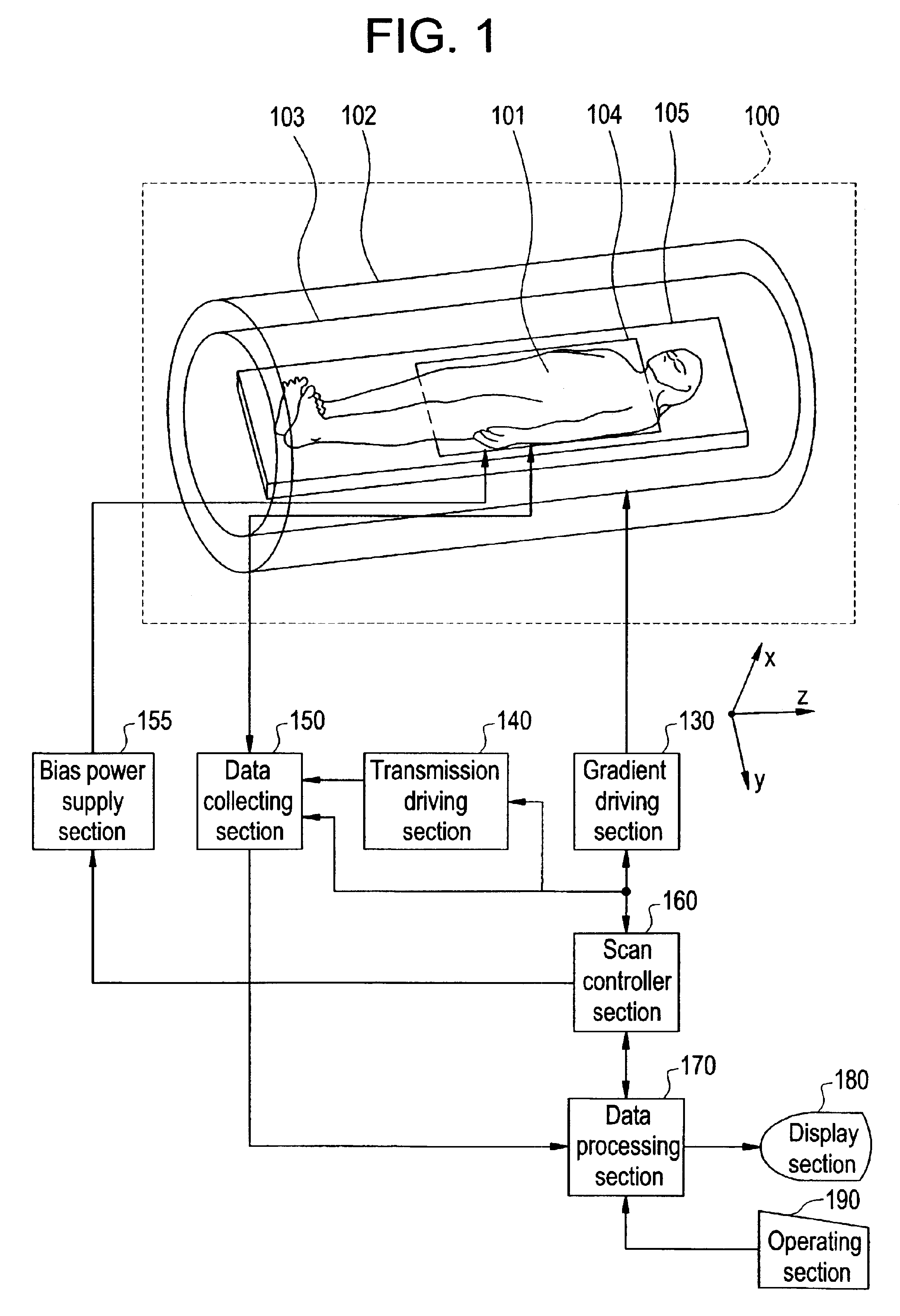
First, an overall configuration of a magnetic. resonance imaging apparatus in accordance with Embodiment 1 will be described. FIG. 1 is a block diagram showing the overall configuration of the magnetic resonance imaging apparatus in accordance with Embodiment 1 of the present invention. In FIG. 1, the magnetic resonance imaging apparatus has a magnet system 100. The magnet system 100 has a main magnetic field coil section 102, a gradient coil section 103, And an RF coil section 104. With the exception of the RF coil section 104, these coil sections have a generally cylindrical shape and are concentrically disposed. A subject to be imaged 101 is rested on a cradle 105 and carried into and out of a generally cylindrical internal space (bore) of the magnet system 100 by carrier means, which is not shown.

The main magnetic field coil section 102 generates a static magnetic field in the internal space of the magnet system 100. The direction of the static magnetic field is ge...

embodiment 2

While the switching element that operates to open and close the parallel resonant circuit by the diode is employed in Embodiment 1, a relay may be operated as the switching element. Therefore, the present embodiment shows a case in which a relay is employed as the switching element.

FIG. 6 is a circuit diagram showing a particular configuration of an RF coil in accordance with Embodiment 2. The RF coil section 600 corresponds to the RF coil section 104 shown in FIG. 1, and since the remaining configuration is similar to that shown in FIG. 1, detailed description of such configuration will be omitted here.

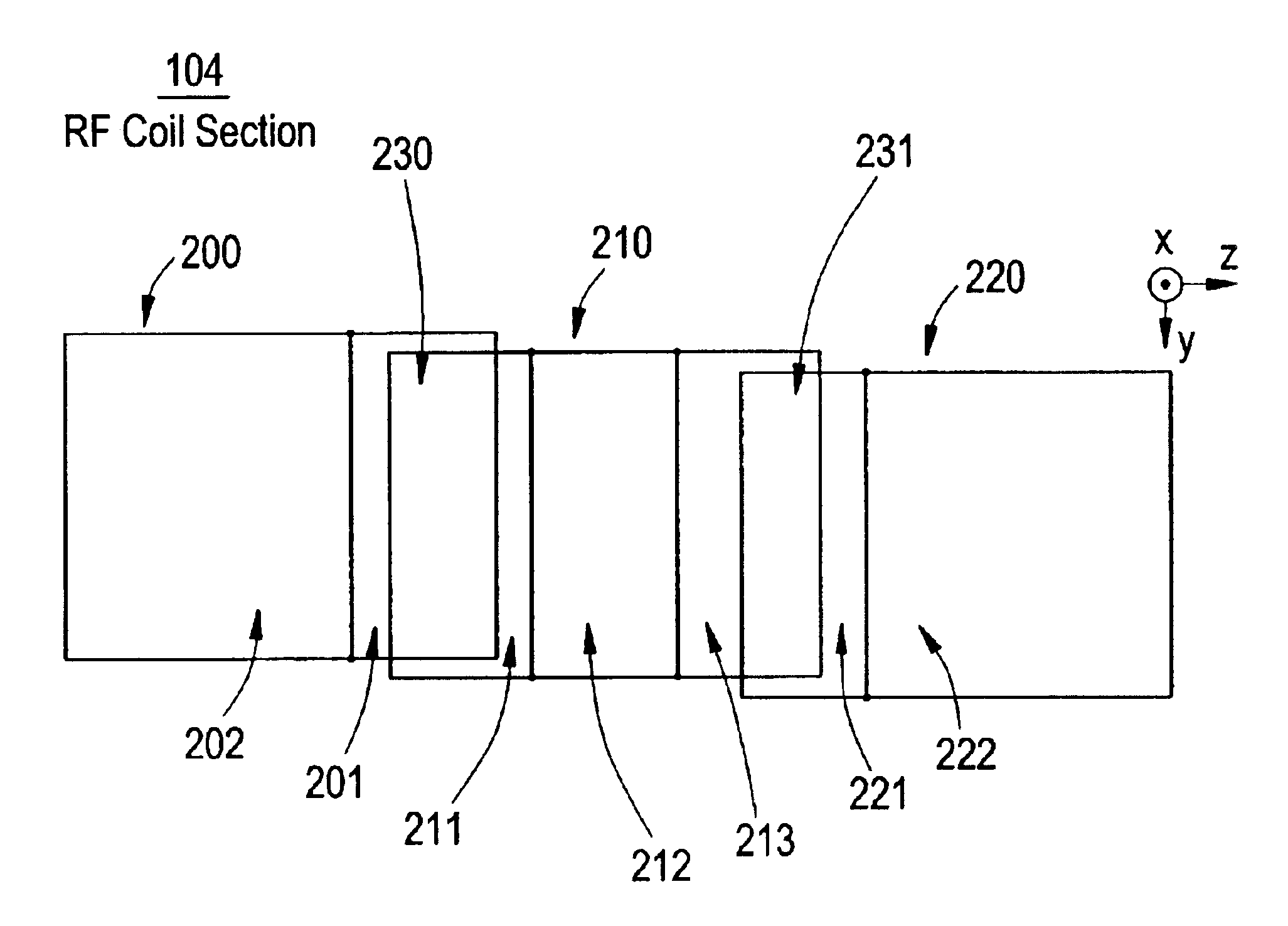
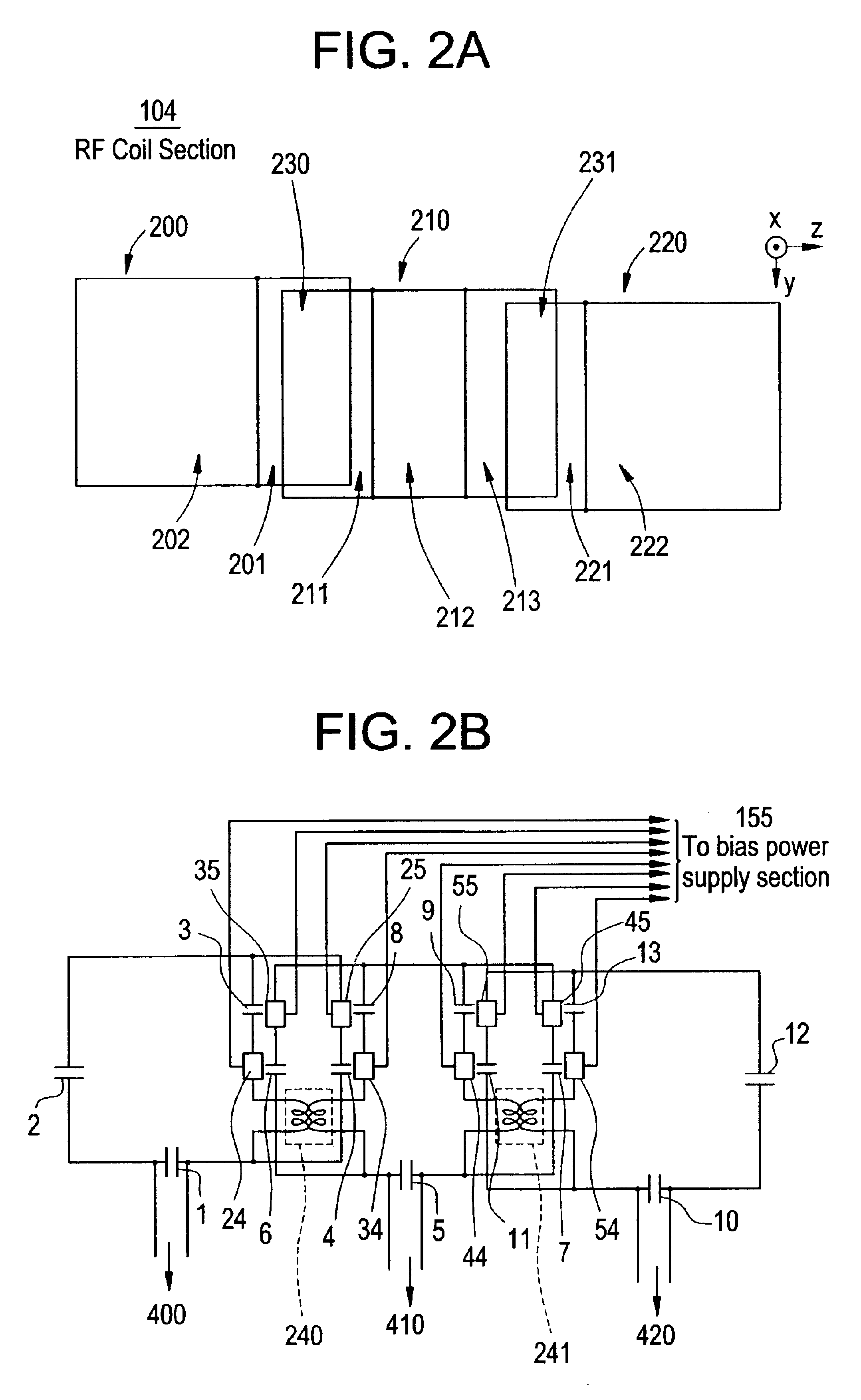
The RF coil section 600 is comprised of loops 200-220, and the loops 200-220 are comprised of first small loops 201-221 and 213, and second small loops 202-222. A switching element 601 is provided in an end portion of a loop line shared by the first and second small loops 201 and 202. Similarly, switching elements 602-604 are provided in an end portion of a loop line shared by the fi...


PUM


Abstract

For the purpose of changing the geometry of and spacing between loop coils incorporated into an RF coil without moving the RF coil, a first plurality of loops having a geometry optimized for a square sum method employing a phased array, and a second plurality of small loops having a geometry optimized for a sensitivity encoding method are switched by switching elements for an open/close operation using a diode, and at the same time, a first decoupling means and a second decoupling means are switched. Thus, an operator is not required to replace the RF coil positioned on a cradle, and the first plurality of loops for the square sum method employing a phased array and the second plurality of small loops for the sensitivity encoding method can be switched by electronic switching and can be used as RF coils.

Description

CROSS REFERENCE TO RELATED APPLICATIONSThis application claims the benefit of Japanese Application No. 2002-056088 filed Mar. 1, 2002.BACKGROUND OF THE INVENTIONThe present invention relates to an RF coil and a magnetic resonance imaging apparatus in which magnetic resonance signals are received by a plurality of coils.Recent magnetic resonance imaging apparatuses employ an RF (radio frequency) coil to generate an electromagnetic field for producing nuclear magnetic resonance in a subject, and receive signals of the magnetic resonance. There have been proposed methods involving providing a plurality of RF coils, Fourier-transforming magnetic resonance signals from the plurality of RF coils, and combining a resulting plurality of images into a new image.These methods include a method involving obtaining the square sum of a plurality of images employing a phased array, and a sensitivity encoding method involving acquiring a plurality of wraparound images, and arithmetically separating...

Claims


Application Information

Patent Timeline
IPC IPC(8): G01R33/34G01R33/3415G01R33/32G01R33/36A61B5/055
CPCG01R33/365G01R33/3415
Inventor YOSHIDA, MASARU
Owner GE MEDICAL SYST GLOBAL TECH CO LLC
Why Eureka
Try Eureka