Scanning interferometer for aspheric surfaces and wavefronts

an interferometer and aspheric surface technology, applied in the field of interferometry, can solve the problems of difficult measurement of aspheric surfaces and wavefronts, and rare and expensive materials

Inactive Publication Date: 2005-04-12
ZYGO CORPORATION
View PDF14 Cites 57 Cited by
  • Summary
  • Abstract
  • Description
  • Claims
  • Application Information

AI Technical Summary

Benefits of technology

According to another aspect of the invention, a test-set up is calibrated absolutely by measuring an aspherical surface of known shape in the same way as an unknown aspherical surface would be probed, i.e., by scanning axially. This known surface could be a parabola, for instance, which can be measured absolutely with the help of a known plane mirror and a known spherical mirror using known procedures available to measure those surfaces in an absolute manner. Another possibility is to use a lens with spherical surfaces used in transmission together with a known auto-collimation mirror. The lens can be measured in transmission beforehand in an absolute manner with the use of other conjugates.
According to another aspect of the invention, spherical surfaces, mildly aspheric surfaces, and mildly aspheric surfaces that have more than one departure from a sphere can be measured by using the inventive procedures to locate the zone of contact, unwrap the measured phase values and calculate the phase difference between a zone and the center of the interferogram.

Problems solved by technology

In addition, lens surfaces in multi-element lithography lenses operating at wavelengths of 193 nm and 157 nm are made aspherical to lower the number of elements made, which are of rare and expensive materials.
So even the fundamental single lens element with either spherical or aspherical surfaces can only be tested properly if one is able to deal with aspherical wavefronts in a test set-up.
The measurement of aspherical surfaces and wavefronts has been very difficult because of the large departure from the best fitting sphere.
But, it is obvious that the same difficulties exist for this type of testing because, again, an aspherical wavefront is produced.
Nevertheless, the final accuracy is questionable because of accumulation of measurement errors and the uncertainty of the homogeneity within the lens material.
While these techniques have utility for many applications, they are limited in their operational capabilities or precision compared with those needed for today's evolving lithography applications.
Contacting and non-contacting stylus based profilers mechanically scan the aspherical surface under test and, therefore, are slow because they measure only a few data points at a time.
Slow techniques are very susceptible to measurement errors due to temperature variations during the measurement.
The same limitations apply to contacting and non-contacting stylus based coordinate measuring machines.
Scanning white light interferometers have many of the same limitations as spherical wavefront interferometers.
Lateral and radial shearing interferometers usually measure the slope of the surface under test and thereby introduce measurement errors during the reconstruction of the surface under test via integration of the slopes.
This latter type of limitation applies to differential types of profiling techniques as well.
Sub-aperture stitching interferometers introduce serious measurement errors in the stitching process.
Interferometers using computer generated holograms are susceptible to errors introduced by the CGH and stray Moiré patterns.
It is also difficult to calibrate, i.e., know the calibration of the CGH.
Point diffraction interferometers are a class of spherical wavefront interferometers, and therefore, have many of the same limitations, as well as poor lateral spatial resolution.
None of the prior art approaches is entirely satisfactory since each involves a trade-off that places long lead times on the design of the measurement apparatus and method, requires additional fabrication, increases the difficulty of using and calibrating the measurement apparatus, decreases the accuracy and precision, and greatly increases the cost and delivery time of the aspherical optical element.

Method used


Image

  • Scanning interferometer for aspheric surfaces and wavefronts
  • Scanning interferometer for aspheric surfaces and wavefronts
  • Scanning interferometer for aspheric surfaces and wavefronts

Examples


Embodiment Construction

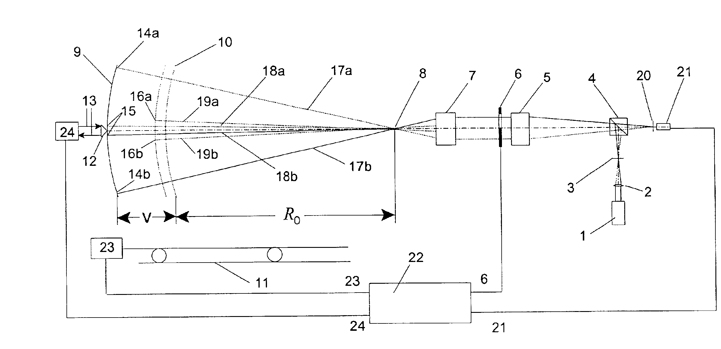
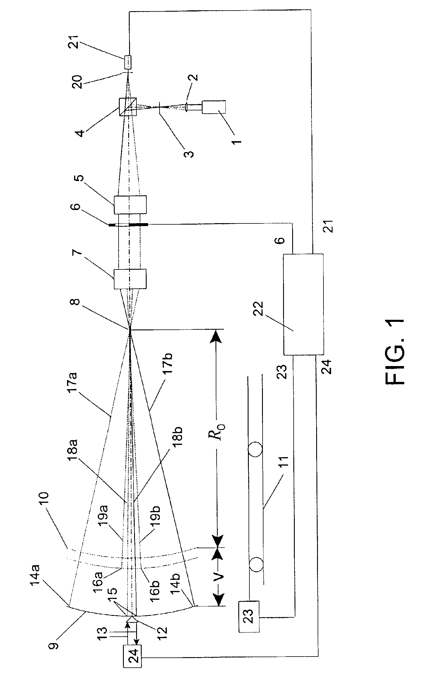
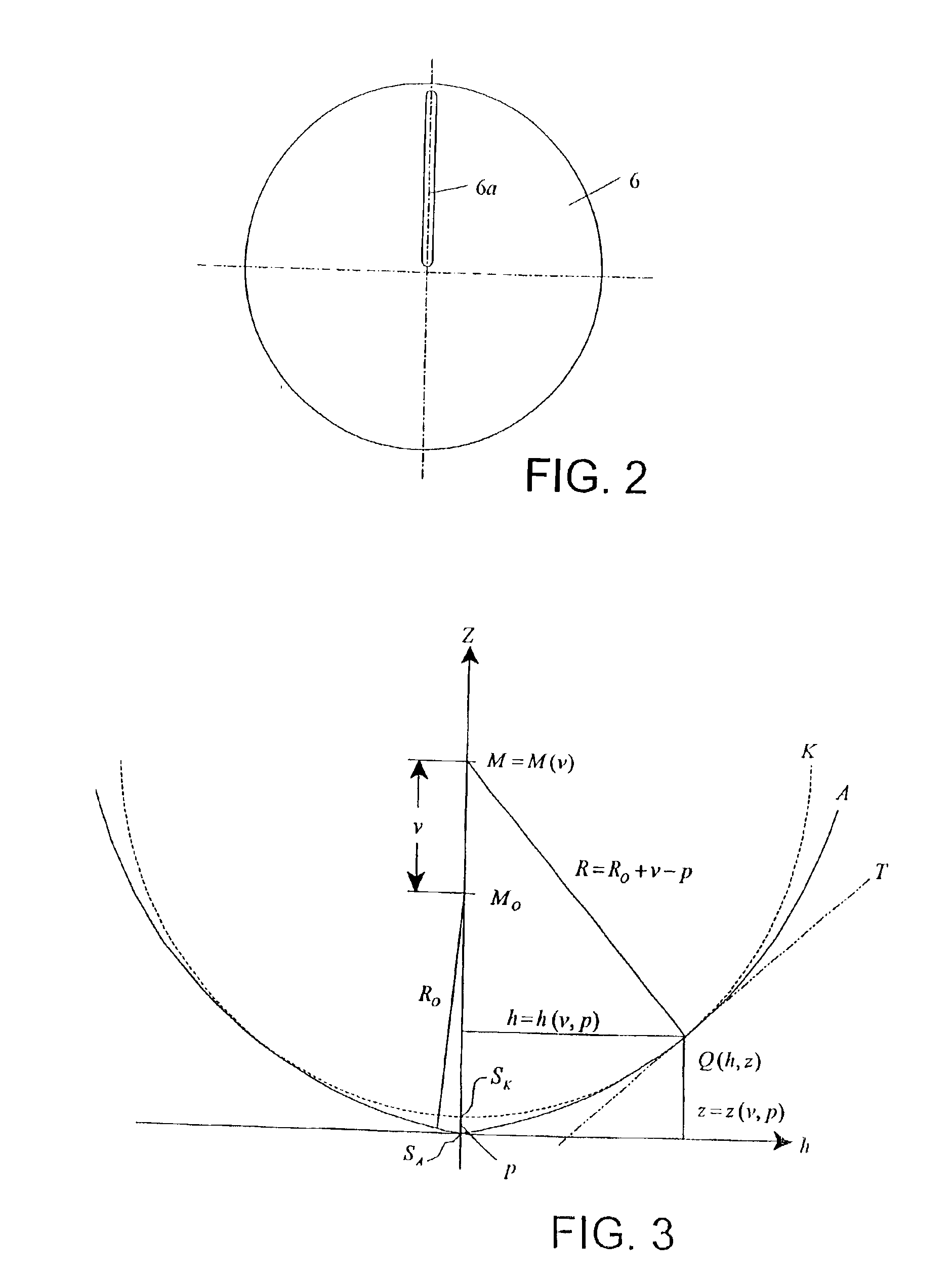
The preferred embodiments together with a associated algorithms will now be described in a more detailed manner. Reference now made to FIG. 1 which shows a simple embodiment of the invention. Light from a coherent light source 1 is focused by a lens 2 into an aperture 3 and hits a beamsplitter 4. The aperture 3 is located in the focal plane of a collimator lens 5, so a plane wave emerges from the collimating lens 5. This plane wave strikes a slit aperture 6, which may be worked into a piece of metal or evaporated onto a glass plate. In FIG. 1, slit aperture 6 lets rays above the optical axis pass and blocks the rays below the optical axis; but a certain region around the optical axis is open all the time, e.g. the slit aperture 6 does not end exactly at the optical axis (See slit 6a in FIG. 2).

In FIG. 1, the rays that pass slit 6a enter a de-collimator lens 7, which focuses the light at a focus point 8 which is an image of aperture 3. Lenses 5 and 7 are highly corrected to have only...


PUM


Abstract

Interferometric scanning method(s) and apparatus for measuring rotationally and non-rotationally symmetric test optics either having aspherical surfaces or that produce aspherical wavefronts. A spherical or partial spherical wavefront is generated from a known origin along an optical axis. The test optic is aligned with respect the optical axis and selectively moved along it relative to the known origin so that the spherical wavefront intersects the test optic at the apex of the aspherical surface and at radial positions where the spherical wavefront and the aspheric surface intersect at points of common tangency. An axial distance, ν, and optical path length, p, are interferometrically measured as the test optic is axially scanned by the spherical wavefront where ν is the distance by which the test optic is moved with respect to the origin and p is the optical path length difference between the apex of an aspherical surface associated with the test optic and the apex of the circles of curvature that intersect the aspherical surface at the common points of tangency. Coordinates of the aspherical surface are calculated wherever the circles of curvature have intersected the aspherical surface and in correspondence with the interferometrically measured distances, ν and p. Afterwards, the shape of the aspheric surface is calculated. Where the test optic comprises a refracting optic a known spherical reflecting surface is provided upstream of the refracting optic for movement along the optical axis and a known wavefront is made to transit the refracting optic, reflects from the known spherical surface, again transits the refracting optic traveling towards the known origin after which the interferogram is formed. In another aspect of the invention, a spherical reference surface is provided to form a Fizeau that is used to generate phase information for measuring spheres, mild aspheres, and multiple mild aspheres.

Description

FIELD OF THE INVENTIONIn general, this invention relates to the field of interferometry and, in particular, to the high accuracy measurement of aspherical surfaces and wavefronts in an absolute manner.BACKGROUND OF THE INVENTIONAspherical surfaces have become more and more important in modern optical systems because they offer a higher number of parameters for simplifying systems while optimizing their performance. This can lead to systems with less surfaces, less weight, smaller dimensions and higher states of correction, to mention only a view advantages. This is especially true in fields where a high number of optical surfaces are not practical, like in astronomical telescopes or normal incidence reflecting surfaces for the EUV wavelength of 13.6 nm used for lithography tools where it is mandatory to keep the number of surfaces as low as possible. In such cases, there is no choice but to use aspherical surfaces. With demands for high quality performance for complete systems opera...

Claims


Application Information

Patent Timeline
Patent Type & Authority Patents(United States)
IPC IPC(8): G01B11/24G01B9/02G01J9/02G01M11/02
CPCG01B11/2441G01M11/0242G01M11/025G01B9/02072G01B9/02039G01B9/02057G01M11/0271G01J9/02G01B2290/65
Inventor KUCHEL, MICHAEL
Owner ZYGO CORPORATION
Why Eureka
Try Eureka