Device for determining and/or monitoring the density and/or the level of a filling material in a container

a technology for determining and/or monitoring the density and/or the level of a filling material in a container, which is applied in the direction of geological measurements, liquid/fluent solid measurements, nuclear radiation detection, etc., can solve the problem of increasing the travel length of the container wall and thus the radiation incidence at the container wall, and achieves reliable measurement

Inactive Publication Date: 2005-04-12
EHNDRESS KHAUZER GMBKH KO KG
View PDF18 Cites 22 Cited by
  • Summary
  • Abstract
  • Description
  • Claims
  • Application Information

AI Technical Summary

Benefits of technology

The object of the invention is to provide a device which enables reliable measu...

Problems solved by technology

The known radiometric level measuring devices have the following disadvantages:The outcome of measurement is affected by the temperature dependency and by the sensitivity of the detector.If relatively long plastic rods are used as a receiving unit, then a large proportion of the light is absorbed; in that case, amplitude evaluation is of little use.Extraneous sources that are not part of the measurement setup adulterate the outcome of measurement.Different wall thicknesse...

Method used


Image

  • Device for determining and/or monitoring the density and/or the level of a filling material in a container
  • Device for determining and/or monitoring the density and/or the level of a filling material in a container
  • Device for determining and/or monitoring the density and/or the level of a filling material in a container

Examples


first embodiment

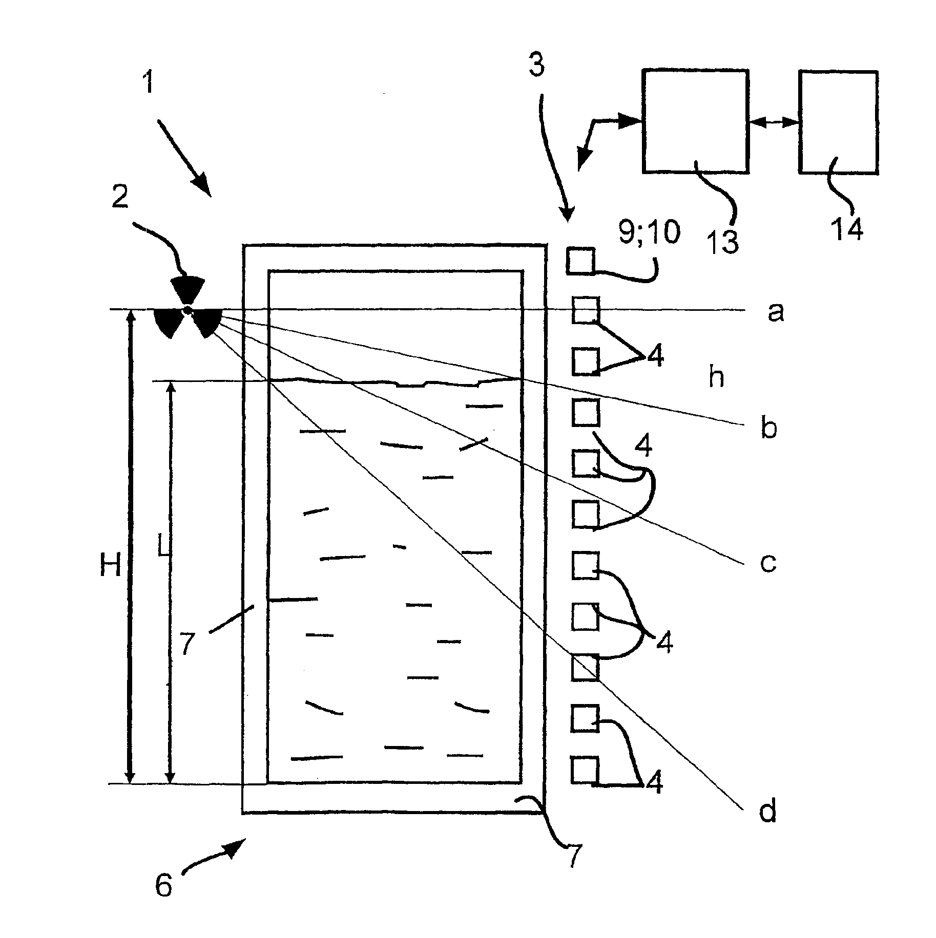
FIG. 1 shows a schematic illustration of the device 1 of the invention. The filling material 8 is stored in the container 6. The fill level of the filling material 8 in the container 6 at the time is marked L.

A point-like transmitting unit 2 that transmits radioactive radiation is disposed in the upper region of the container 6. The radioactive radiation penetrates the container wall 7 and the interior of the container 6 and is received by the detector units 4 that are located on the opposite side of the container 6. The detector units 4 are either individual detectors or detector arrays 5, which are put together from a plurality of individual detectors. One possible embodiment of a detector array 5 is also shown in FIG. 6.

The lower-case letters a, b, c, d stand for instance for four different distances that the radiation travels through the container before it is received by the corresponding detector units 4. It is self-evident that the proportion of the radiation that reaches a d...

second embodiment

In FIG. 4, the device 1 of the invention is shown schematically. This embodiment differs from that shown in FIG. 1 in that a plurality of detector units 4 are each disposed on a respective retaining element 12, and the individual retaining elements 12 are positioned such that the detector units 4 can cover the entire measurement range. The cascading of the individual detectors is moreover done in the case illustrated via a bus line 16. The bus line 16 can connect both individually housed detector units 4 and multiple detector units 4 that form a detector array 5 or that are disposed on a retaining element 12 with one another. Because of this embodiment, for a fundamentally unlimited measurement range, only one regulating / evaluating unit 13 is required. The regulating / evaluating unit 13 interrogates the detector units 4 in succession and subsequently evaluates the measurement data forwarded.

Retroactive expansions of the measurement range can be done at any time without problems in th...

third embodiment

FIG. 5 schematically shows the device 1 of the invention. The difference from the embodiments shown in FIGS. 1 and 4 is primarily in the geometry of the container 6.

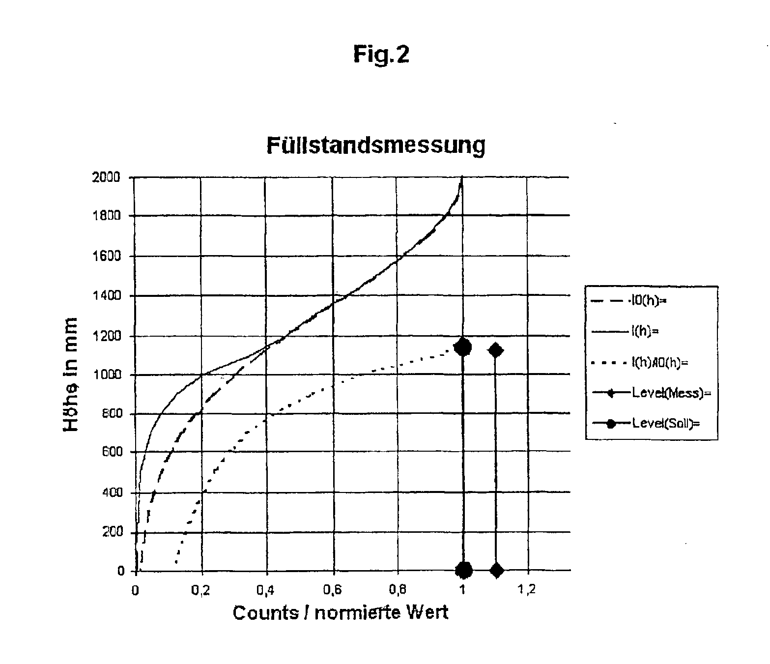
Besides measuring or monitoring the level of a filling material 8 in a container 6, the device of the invention is also—as already mentioned several times—excellently well suited to measuring or monitoring the density of a filling material 8. For the sake of clarity, the following example is referred to: In fluidized bed reactors, the density of the filling material 8, in the normal situation, is not constant above the level L. Because of the fluidization, gases or clouds of dust predominantly occur in the upper region of the container 6 or reactor, while in the lower region the filling material 8 is tightly packed. With conventional measuring instruments, this effect is taken only inadequately into account by assuming that the course of density corresponds with a predetermined characteristic linearization curve. The act...


PUM

PropertyMeasurementUnit
Timeaaaaaaaaaa
Temperatureaaaaaaaaaa
Densityaaaaaaaaaa

Abstract

The invention relates to a device for determining and/or monitoring the density and/or the level (L) of a filling material in a container. A transmitting unit which emits radioactive radiation and a receiving unit which is arranged in such a way that it receives the radioactive radiation or the secondary radiation that is produced by the interaction of the radioactive radiation with the filling material are provided. A regulating/evaluating unit which determines the density and/or the level of the filling material in the container using the measuring data that is supplied by the receiving unit is also provided. The aim of the invention is to provide a device which enables the level or the density of a filling material in a container to be measured reliably. To this end, the receiving unit consists of individual detector units. These detector units are positioned at different distances from the floor of the container, so that each detector unit directly or indirectly, essentially detects the proportion of radiation that passes.

Description

TECHNICAL FIELDThe invention relates to a device for determining and / or monitoring the density and / or the level of a filling material in a container.The device has a transmitting unit that transmits radioactive radiation, and a receiving unit that is disposed such that it receives the radioactive radiation, or the secondary radiation generated by interaction of the radioactive radiation with the filling material, and a regulating / evaluating unit, which from the measurement data furnished by the receiving unit determines the density and / or the level of the filling material in the container.The device of the invention further relates to a device in which the transmitting unit is unnecessary, since the filling material itself already transmits radioactive radiation that is subsequently detected by the receiving unit. This last feature of the invention can be employed for instance in measuring potassium concentration, in monitoring steel scrap for radioactive materials, and in monitorin...

Claims


Application Information

Patent Timeline
IPC IPC(8): G01F23/284G01F23/288G01N23/22G01N9/24
CPCG01F23/288G01N23/22G01N9/24
Inventor DAMM, HARTMUTNEUHAUS, JOACHIMKAMEREIT, WOLFGANG
Owner EHNDRESS KHAUZER GMBKH KO KG
Why Eureka
Try Eureka