

Optical switch
a technology of optical switch and optical light guide, which is applied in the field of optical switch, can solve problems such as troublesome driving
- Summary
- Abstract
- Description
- Claims
- Application Information
AI Technical Summary
Benefits of technology
Problems solved by technology
Method used
Image

Examples
first embodiment
[First Embodiment]
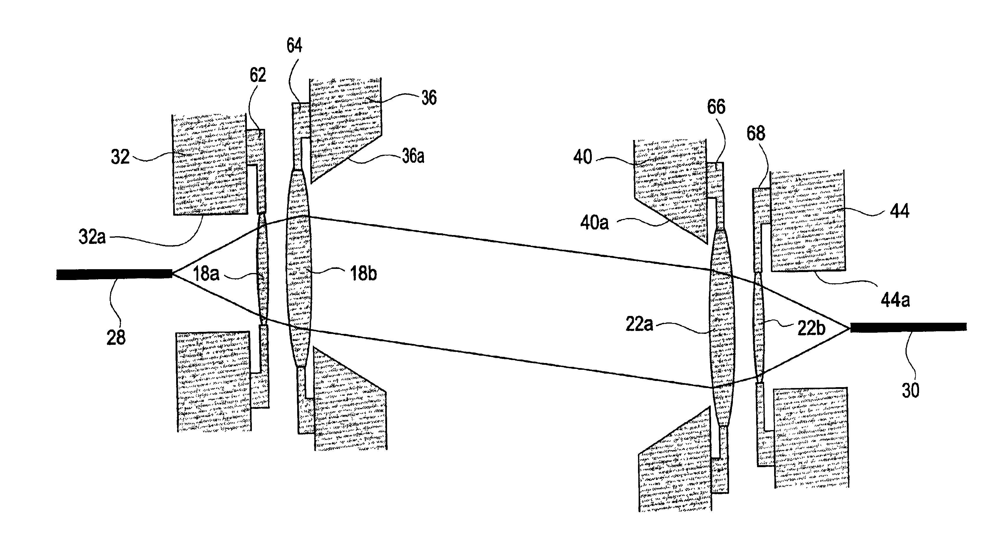
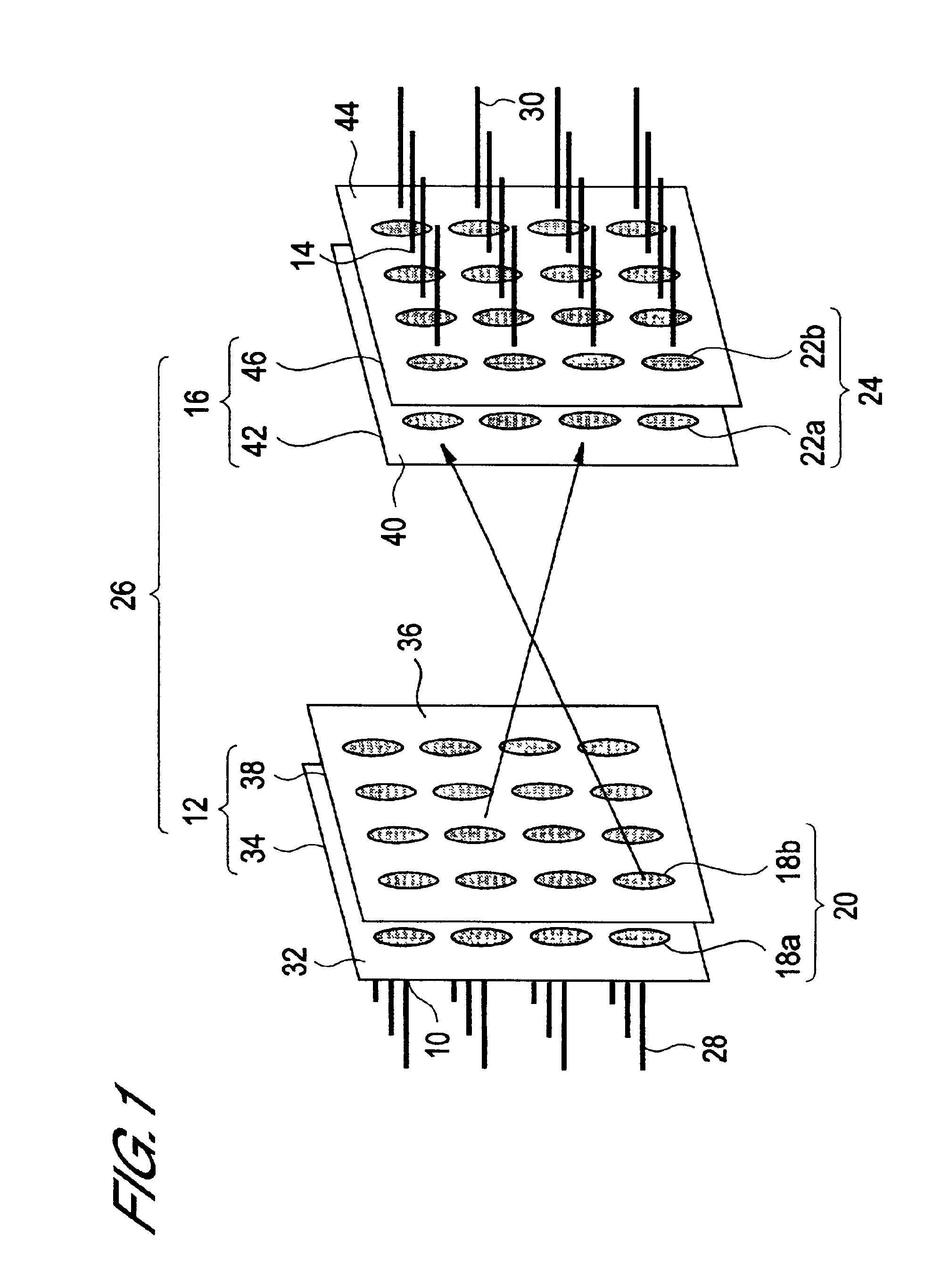
FIG. 1 is a perspective view illustrating the construction of an optical switch according to the first embodiment. This optical switch 26 comprises an input side switching element 12 having a plurality of optical input ports 10 and an output side switching element 16 having a plurality of optical output ports 14. The light rays are shown by the arrows in FIG. 1. With this optical switch, optical signals that are input at any one of the optical input ports 10 are output from any one of the optical output ports 14.
The input side switching element 12 described above comprises an input side optical deflection element group 20 consisting of two optical deflection elements 18a and 18b at each respective optical input port 10. These optical deflection elements 18a and 18b are arranged along the direction of incidence of the optical signals that are directed into the optical input port 10.
Also, the output side switching element 16 described above comprises an output side o...
second embodiment
[Second Embodiment]
FIG. 11 is a view showing the arrangement of an optical switch according to a second embodiment. This optical switch 108 comprises an input side switching element 110 having a plurality of optical input ports 10 and an output side switching element 112 having a plurality of optical output ports 14.
In the input side switching element 110 mentioned above, there is provided an input side optical deflection element group 114 comprising two optical deflection elements 18a and 100a at each respective optical input port 10. These optical deflection elements 18a and 100a are arranged along the direction of incidence of the optical signal that is launched into optical input port 10.
Also, the output side switching element 112 mentioned above comprises an output side optical deflection element group 116 comprising two optical deflection elements 100b and 22b at each respective optical output port 14. These optical deflection elements 100b and 22b are arranged along the direc...
third embodiment
[Third Embodiment]
Next, an optical switch according to a third embodiment will be described referring to the above aspects. In the optical switch of this embodiment, in order to increase the number of channels, an optical system is incorporated that expands the diffraction angle θd of the optical fiber.
The basic construction of an optical switch according to the third embodiment is the same as in the case of the device shown in FIG. 13. Specifically, it comprises an input side optical fiber connected with the optical input port, and output side optical fiber connected with the optical output port, and a collimator system inserted between these optical fibers. Also, it is provided with optical deflection elements constituted by a moveable lens or moveable mirror, respectively, on the input side and output side.
FIG. 17 is a view illustrating the construction of a detail of an optical switch according to the third embodiment. FIG. 17 shows an input side collimator lens 120 and an input...
PUM
 Abstract
Description
Claims
Application Information