Apparatus and method for transmitting and receiving for image

a technology of transmitting and receiving apparatus, applied in the direction of digital output to print units, instruments, data switching networks, etc., can solve the problems of user complex operations and delay in mail delivery with mail servers

Inactive Publication Date: 2005-04-12
MATSUSHITA GRAPHIC COMM SYST INC
View PDF14 Cites 48 Cited by
  • Summary
  • Abstract
  • Description
  • Claims
  • Application Information

AI Technical Summary

Benefits of technology

It is an object of the present invention to provide an image transmitting apparatus, which can obtain an IP address for a communication terminal automatically and which can transmit image data to the communication terminal directly in a network in which a DHCP is introduced.
Also, it is an object of the present invention to provide an image receiving apparatus, which can obtain an IP address for a communication terminal automatically and which can receive image data from the communication terminal directly in a network in which a DHCP is introduced.,
Moreover, it is an object of the present invention to provide an image transmitting method, which can obtain an IP address for a communication terminal automatically and which can transmit image data from the communication terminal directly in a network in which a DHCP is introduced.
Furthermore, it is an object of the present invention to provide an image receiving method, which can obtain an IP address for a communication terminal automatically and which can receive image data from the communication terminal directly in a network in which a DHCP is introduced.
This makes it possible to perform an image transmission using a communication protocol, which needs an IP address for a receiver side, in accordance with, for example, a DHCP protocol in the network in which an IP address is assigned to a communication terminal from an outer section.
This makes it possible to perform an image reception using a communication protocol, which needs an IP address for a receiver side, in accordance with, for example, a DHCP protocol in the network in which an IP address is assigned to a communication terminal from an outer section.

Problems solved by technology

However, there is a possibility that delay of mail delivery with the mail server will occur when image data is transmitted to the PC via the mail server.
Moreover, similar to the case in which e-mail is generally received, since the operator must activate a mailer on PC and obtain access to the mail server, complicated operations are required of the user.

Method used


Image

  • Apparatus and method for transmitting and receiving for image
  • Apparatus and method for transmitting and receiving for image
  • Apparatus and method for transmitting and receiving for image

Examples


first embodiment

(First Embodiment)

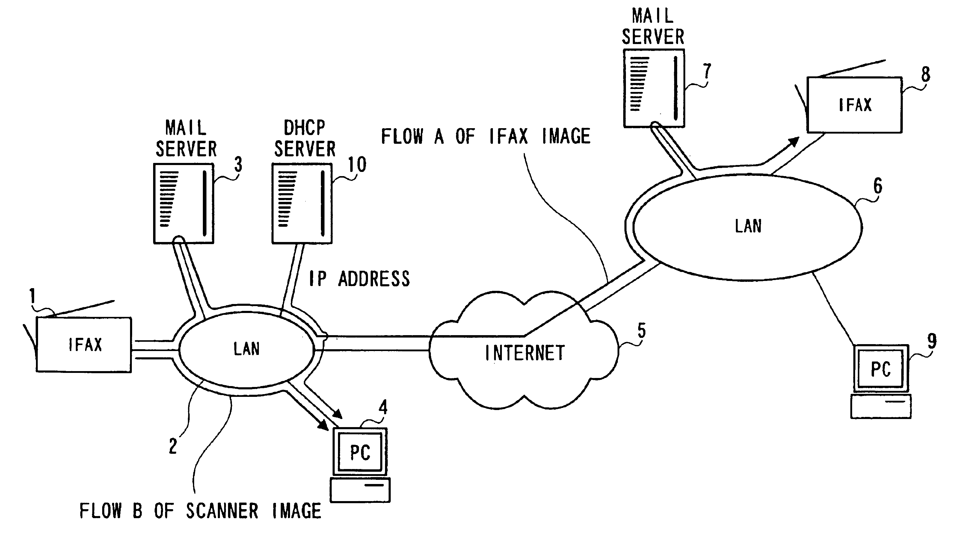
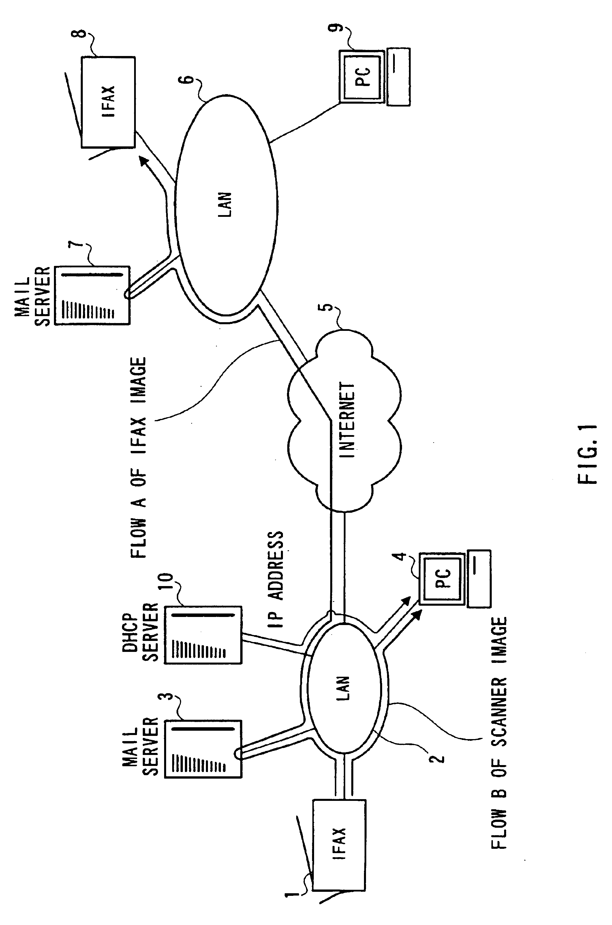
FIG. 1 is a conceptual view showing a network system in which an image transmitting apparatus and an image receiving apparatus of according to a first embodiment of the present invention operate.

An Internet facsimile apparatus 1 (hereinafter referred to as IFAX) according to the first embodiment is connected to a local area network (LAN) 2. A mail server 3 and a personal computer (PC) 4, which are installed in the same local area as the IFAX 1, are connected to the LAN 2. Though a large number of PCs 4 is provided, one of them is illustrated for convenience in explanation.

Also, the LAN 2 is connected to the Internet 5. The other LAN 6 is also connected to this Internet 5. A mail server 7, an IFAX 8, and a PC 9 are connected to this LAN 6.

IFAX 1 transmits and receives image data between, for example, the IFAX 8 and the IFAX 1 by use of e-mail. As shown by an arrow A of FIG. 1, e-mail is first transmitted to the mail server 3 of the transmitter side. The mail server ...

second embodiment

(Second Embodiment)

Next, an explanation will be given of the IFAX according to the second embodiment of the present invention.

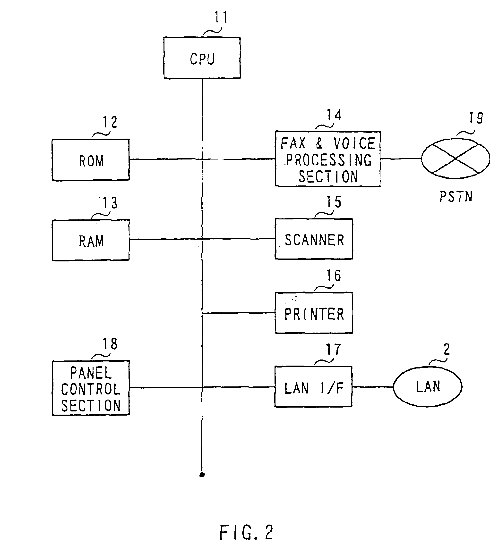
FIG. 12 is a functional block diagram showing the IFAX processing section of the IFAX according to the second embodiment. Regarding the same configuration as that of the first embodiment shown in FIG. 1, the same reference numerals as those of the first embodiment are added thereto, and the explanation is omitted.

A one-touch registering section 1201 assigns a desired destination mail address to the one-touch button of the panel control section 18. The one-touch registering section 1201 controls the registration made by the operator, and writes the content of registration to a one-touch button table stored in a one-touch button table area 1202 of RAM 13. Also, The one-touch registering section 1201 registers whether this destination mail address is used for IFAX transmission processing or network scanner processing at the same time.

A one-touch button number 13...


PUM


Abstract

A RARP processing section of a network scanner obtains a MAC address corresponding to a user name from a MAC address table, and broadcasts a RARP request by use of this MAC address. While, a PC sends a pair of a self-IP address and a mail address to a RARP processing section in response to the RARP request. After obtaining an IP address of this PC, a scanner scans an original, and generates e-mail to which the image is appended. Next, an SMTP transmitting section directly transmits the generated e-mail to the PC. At this time, the SMTP transmitting section uses the IP address of PC obtained by the RARP processing section. In the network to which HDCP is introduced, the network scanner automatically obtains the IP address of PC, and directly transmits image data to the PC.

Description

BACKGROUND OF THE INVENTION1. Field of the InventionThe present invention relates to an image transmitting and receiving apparatus, which operates on an IP network. Also, the present invention relates to an image transmitting and receiving method on an IP network.2. Description of the Related ArtIn a TCP / IP network, there is a necessity to assign an IP address per client in order to allow control for transmitting and receiving data packet between clients. An means for performing this IP address assignment automatically, there is a DHCP (Dynamic Host Configuration Protocol). A server for a DHCP assigns an IP address in response to a request from the client. Generally, the client transmits a request message when the client's apparatus is turned on, and the server that has received this request assigns a vacant IP address to the client. For this reason, the IP address for the client differs every time when the client's apparatus is started.While there is conventionally proposed an Inte...

Claims


Application Information

Patent Timeline
Patent Type & Authority Patents(United States)
IPC IPC(8): H04N1/00H04N1/32G06F3/12G06F13/00H04L12/28H04L12/58H04L12/66H04L12/70
CPCH04N1/00214H04N1/00217H04N1/00222H04N1/00225H04N1/32037H04N2201/3208H04N1/32122H04N2201/0065H04N2201/0086H04N2201/3204
Inventor TOYODA, KIYOSHI
Owner MATSUSHITA GRAPHIC COMM SYST INC
Why Eureka
Try Eureka