Al technical title is built by PatSnap Al team. It summarizes the technical point description of the patent document.
a technology of fixture system and woodworking machinery, which is applied in the field of shop-made jigs and fixtures, can solve the problems of compromising the fit of the stop in the t-slot of typical jigs, affecting the fit of the stop, and not being able to lock securely
Inactive Publication Date: 2005-04-19
KREG ENTERPRISES
View PDF16 Cites 53 Cited by
Summary
Abstract
Description
Claims
Application Information
AI Technical Summary
This helps you quickly interpret patents by identifying the three key elements:
Problems solved by technology
Method used
Benefits of technology
[0012]In another aspect, the stop is pivotable about a longitudinal axis and is generally L-shaped, having a top leg with a rear surface that faces the woodworking support and that is concave toward the woodworking support, and a bottom leg connected to a lower end of the top leg, the bottom leg extending from the top leg away from the woodworking support. The concavity of the top leg provides clearance with a zero clearance board and makes the stop adaptable to a wide variety of different systems and different fence heights.
[0013]In another aspect, the bottom leg o
Problems solved by technology
One problem is with the fit of the stop in the T-slot of typical jig and fixture systems.
It is typical that the stops available do not lock securely in the T-slot.
There is typically a slight variation in the extrusions which compromises the fit.
U.S. Pat. No. 5,337,641 teaches that the stop can be bolted in the down position, but this requires threading a bolt through the stop into the base, which is tedious.
Typical stops available are not designed to allow cu
Method used
Image
Click on the blue label to locate the original text in one second.
Reading with bidirectional positioning of images and text.
Examples
Embodiment Construction
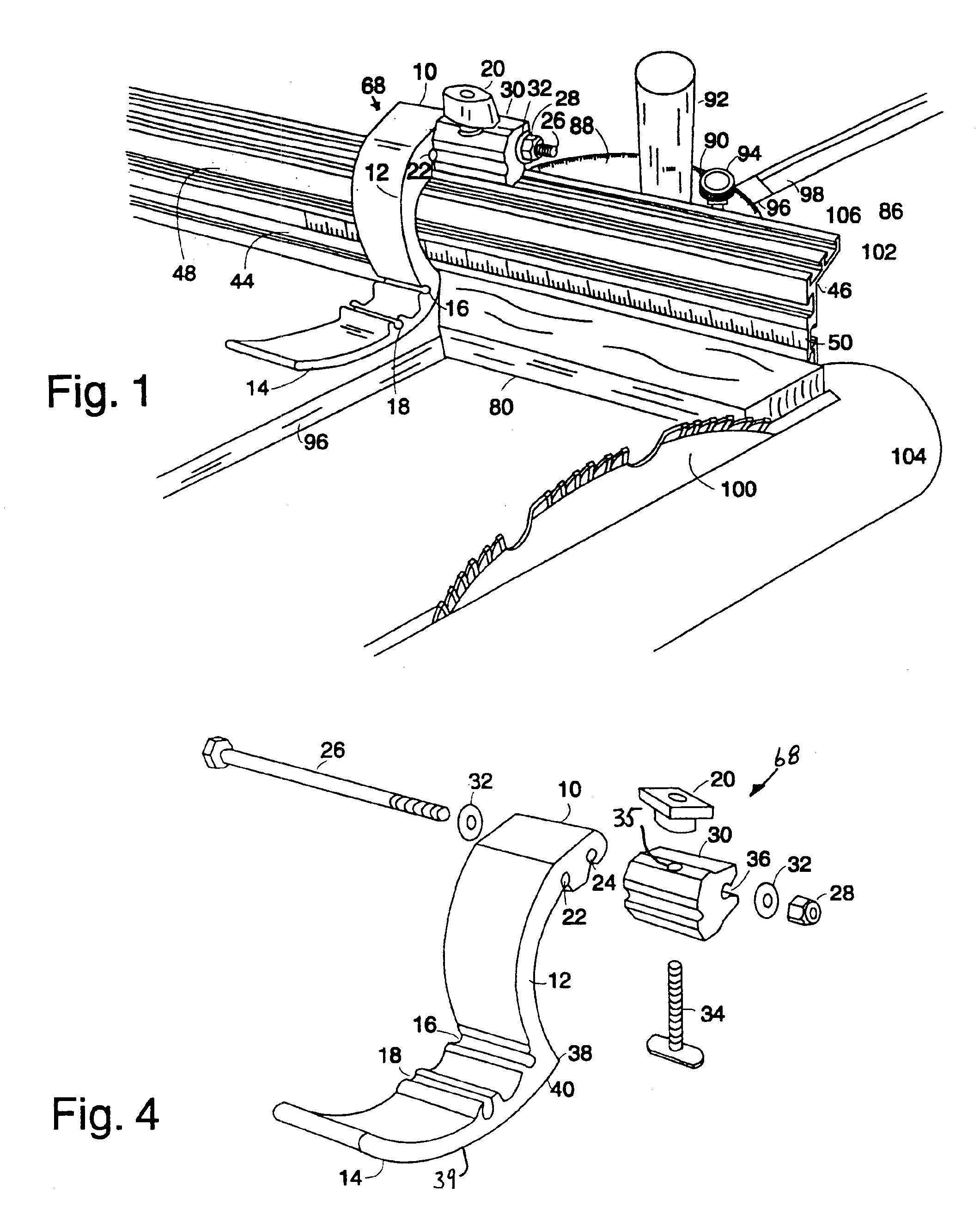
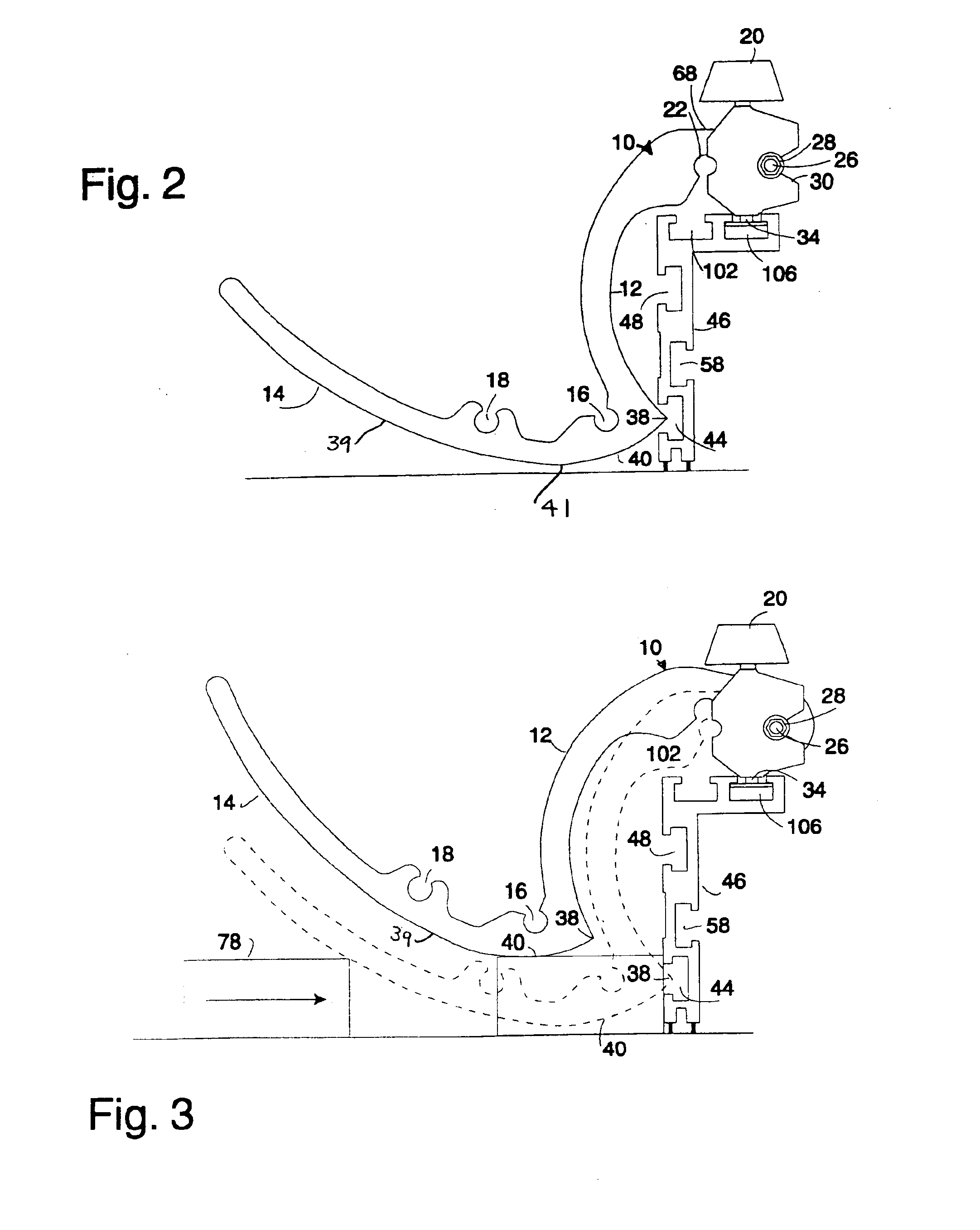
[0044]FIG. 1 illustrates a curved flip stop assembly of the invention 68 mounted to the fence track 46, which is one type of woodworking support, and miter guide 88 of U.S. Pat. No. 5,768,966. A miter gauge 88 which is attached to a miter gauge bar 96 fits into the table saw miter slot 98 and is used to control the workpiece as it is moved past the saw blade 100. A flip stop assembly 68 is shown on the L shaped track 46 which includes a curved L shaped flip stop arm 10 which is attached to a base 30 by a ¼″ bolt 26 and a lock nut 28. The flip stop assembly 68 is used to crosscut boards to length by measuring the distance between the end of the board 80 and the saw blade 100. The end of the board is pressed against the stop arm 10 while the other end is cut with the blade 100. When the flip stop assembly 68 is not in use the flip stop arm 10 is flipped out of the way. The flip stop assembly 68 is slideable along the length of a track by loosening knob 20 to loosen the head of the bol...
PUM
Property
Measurement
Unit
Angle
aaaaa
aaaaa
Width
aaaaa
aaaaa
Abstract
A woodworking machinery jig and fixture system includes a track which is or may be attached to a fence, a convex-concave curved flip stop and a base which mounts the stop to the track. The stop has a projecting portion which penetrates the plane of the fence so the stop isn't lifted by the point of a mitered board. The stop also has a lower convex surface which faces the work support surface and curves up at both ends. The top leg of the stop is concave toward the fence to allow clearance for a zero-clearance board and make the stop adaptable to different track and fence configurations. The base has opposite sides of different widths bordered by steps on one side and a ramp on the other side so the base can be used in a large range of T-track slot widths. The arm mounting hole of the base is offset from the base mounting so as to provide an offset to accommodate a ¾″ zero clearance board by turning the base a half turn relative to the slot. A two slot track is provided in which one of the slots can mount a sliding measurement tape or a base, and the other slot can also mount a base. In another track, a sidewall flange is provided which can be filed to accurately fit into a miter gauge slot of a cutting tool table.
Description
CROSS-REFERENCE TO RELATED APPLICATION[0001]This claims the benefit of U.S. Provisional Patent Application No. 60 / 317,994 filed Sep. 7, 2001.STATEMENT CONCERNING FEDERALLY SPONSORED RESEARCH OR DEVELOPMENT[0002]Not applicable.FIELD OF THE INVENTION[0003]This invention relates to shop made jigs and fixtures for positioning, aligning, guiding and / or holding a workpiece on metalworking or woodworking machines during a cutting or shaping operation.BACKGROUND OF THE INVENTION[0004]U.S. Pat. Nos. 5,337,641, 5,617,909 and 5,768,966, which are hereby incorporated by reference, disclose improved jigs and fixtures for aligning, guiding and or holding a workpiece as it is worked, for example as it is cut, drilled or routed. While the jigs and fixtures disclosed in U.S. Pat. Nos. 5,337,641, 5,617,909 and 5,768,966 represent a significant advance in the art, room still exists for improvement, particularly in the following respects.[0005]One problem is with the fit of the stop in the T-slot of ty...
Claims
Application Information
Patent Timeline
Application Date:The date an application was filed.
Publication Date:The date a patent or application was officially published.
First Publication Date:The earliest publication date of a patent with the same application number.
Issue Date:Publication date of the patent grant document.
PCT Entry Date:The Entry date of PCT National Phase.
Estimated Expiry Date:The statutory expiry date of a patent right according to the Patent Law, and it is the longest term of protection that the patent right can achieve without the termination of the patent right due to other reasons(Term extension factor has been taken into account ).
Invalid Date:Actual expiry date is based on effective date or publication date of legal transaction data of invalid patent.