Valve seal assembly for rotary valve engine

Active Publication Date: 2005-04-19
COATES GEORGE J
View PDF8 Cites 25 Cited by
  • Summary
  • Abstract
  • Description
  • Claims
  • Application Information

AI Technical Summary

Benefits of technology

[0014]A valve seal for a rotary valve assembly for use in an internal combustion engine of the piston and cylinder type, wherein the cylinder head/combustion chamber is designed for high compression and of long stroke, such as a diesel engine, the rotary valves and the valve

Problems solved by technology

In short stroke engines, the assembly works without modification because of the relatively short stroke of the piston and the resultant pressures developed.
However in long stroke engines, such as diesels, in which the compression is significantly greater than in a conventional internal combustion engine, and which compression actually results i

Method used


Image

  • Valve seal assembly for rotary valve engine
  • Valve seal assembly for rotary valve engine
  • Valve seal assembly for rotary valve engine

Examples


Embodiment Construction

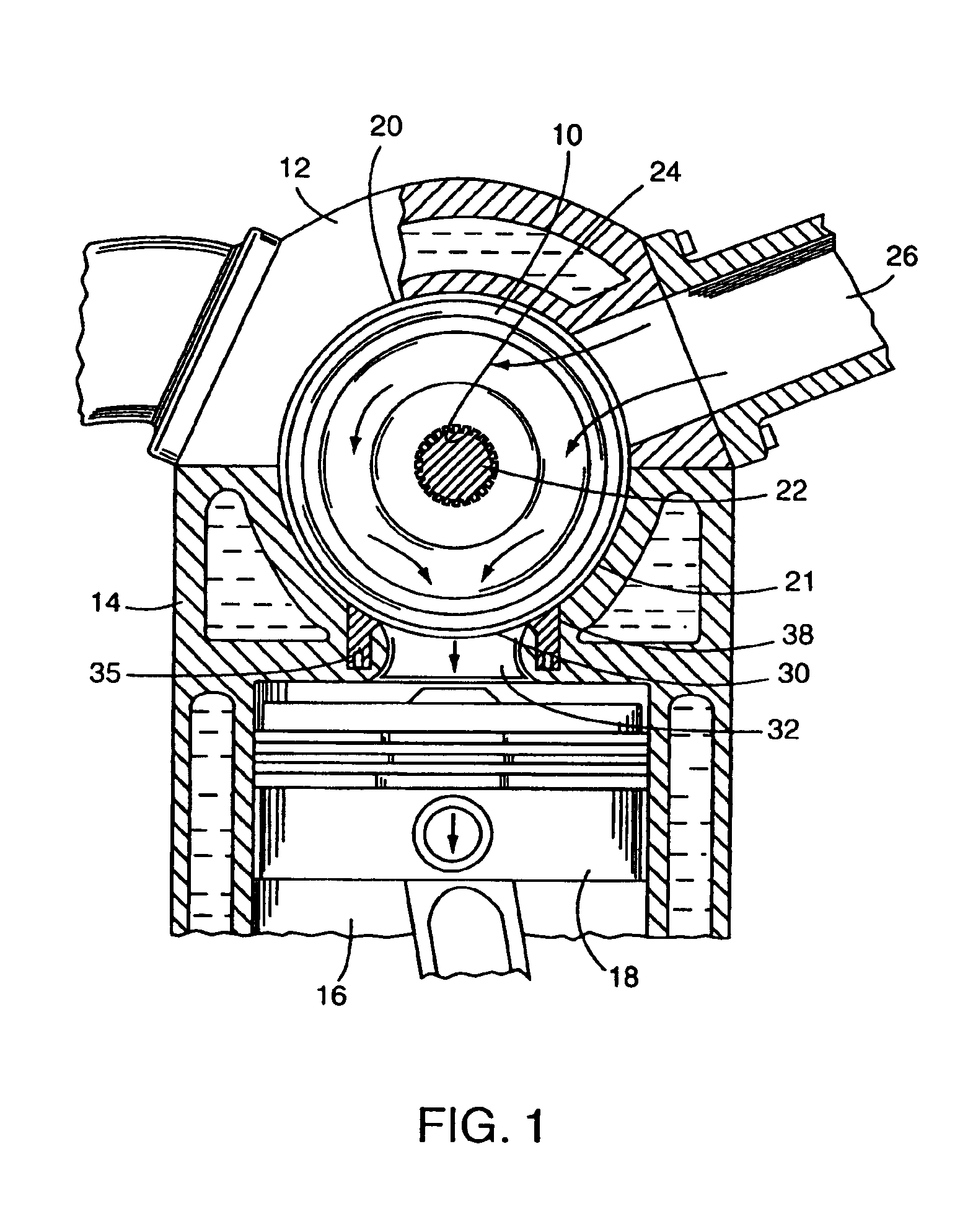
[0020]Referring to FIG. 1, there is illustrated an end cross-sectional view of an embodiment of the spherical rotary valve assembly of Applicant's prior patents detailing the relationship between a rotary intake valve 10 enclosed within an upper half 12 and a lower half 14 of a split head assembly. The split head assembly is secured to an engine block having cylinder 16 within which piston 18 reciprocates.

[0021]The split head assembly comprising upper half 12 and lower half 14 defines a drum accommodating cavity 20 within which rotary intake valve 10 is positioned. Rotary intake valve 10 is positioned on shaft 22 which passes through a centrally positioned aperture 24 on the rotary intake valve 10. As discussed in detail in Applicant's prior patents heretofore set forth, rotary intake valve 10 provides for communication between fuel air inlet port 26 and cylinder 16 by means of an aperture 30 positioned on the spherical periphery 21 of the rotary valve 10 which comes into successive...


PUM


Abstract

A valve seal for a rotary valve assembly for use in an internal combustion engine of the piston and cylinder type, wherein the cylinder head/combustion chamber is designed for high compression and of long stroke, such as a diesel engine, the rotary valves and the valve seals being positioned in relationship so as to permit charging of the cylinder with a fuel/air mixture and evacuation of spent gases, and to regulate the pressure within the valve seal and valve seat and hence regulate the pressure between the valve seal and the rotary valve.

Description

BACKGROUND OF THE INVENTION[0001]1. Field of the Invention[0002]The present invention relates to an internal combustion engine of the piston-cylinder type having a spherical rotary valve assembly for the introduction of the fuel / air mixture to the cylinder and the evacuation of the exhaust gases, and is particularly directed to the floating valve seals for such rotary valve assembly and means for regulating pressure therein, particularly in long stroke, high compression engines such as diesels.[0003]2. Description of the Prior Art[0004]The Applicant herein has directed considerable attention to the internal combustion engine of the piston-cylinder type and in particular to the replacement of the poppet valve system, including the poppet valve, springs, mountings and associated cam shaft, with a spherical rotary valve assembly for the introduction of the fuel air mixture into the cylinder and for the evacuation of the exhaust gases. Applicant is the named inventor in U.S. Pat. No. 4,...

Claims


Application Information

Patent Timeline
IPC IPC(8): F01L7/00F01L7/02F01L7/16
CPCF01L7/021F01L7/16F01L2101/02F01L7/10F01L2301/02F01L7/00
Inventor COATES, GEORGE J.
Owner COATES GEORGE J
Why Eureka
Try Eureka