Air-fuel ratio control apparatus for internal combustion engine

a technology of air-fuel ratio and control apparatus, which is applied in the direction of electric control, combustion-air/fuel-air treatment, instruments, etc., can solve the problems of unfavorable acceleration performance, inability to maintain the air-fuel ratio at the theoretical air-fuel ratio, and unwanted introduction of purge air of high purge ratio (i.e., remarkably rich purge air) into the intake system of the engine, so as to achieve high accuracy without degrading acceleration performance

Inactive Publication Date: 2005-04-19
MITSUBISHI ELECTRIC CORP
View PDF6 Cites 15 Cited by
  • Summary
  • Abstract
  • Description
  • Claims
  • Application Information

AI Technical Summary

Benefits of technology

[0019]With the arrangement of the air-fuel ratio control apparatus for the internal combustion engine described above, the air-fuel ratio can be controlled with high accuracy without degrading the acceleration performance even in the case where the engine operation is accelerated from the operation state where the rich purge air of a high purge ratio is being introduced by virtue of such arrangement that the purge air concentration correcting coefficient is reset to the initial value when the purge air concentration correcting coefficient becomes smaller than the predetermined value inclusive (indicating leanness of the air-fuel mixture) and when acceleration of the motor vehicle is detected.

Problems solved by technology

Consequently, it is impossible to maintain the air-fuel ratio at the theoretical air-fuel ratio (=14.7) during a time period taken for the purge ratio to become steady.
The air-fuel ratio control apparatus for the internal combustion engine known heretofore suffers a problem that even when the fuel injection quantity is corrected with the purge air concentration arithmetically determined from the purge ratio and the air-fuel ratio feedback correcting coefficient so that the air-fuel ratio feedback correcting coefficient becomes constant, the purge air of high purge ratio (i.e., remarkably rich purge air) will unwantedly be introduced in the intake system of the engine because it takes a lot of time for the purge air concentration correcting coefficient to be updated to a value for enriching the air-fuel mixture in response to lowering of the purge ratio for the enriching demand upon acceleration of the engine.

Method used


Image

  • Air-fuel ratio control apparatus for internal combustion engine
  • Air-fuel ratio control apparatus for internal combustion engine
  • Air-fuel ratio control apparatus for internal combustion engine

Examples


embodiment 1

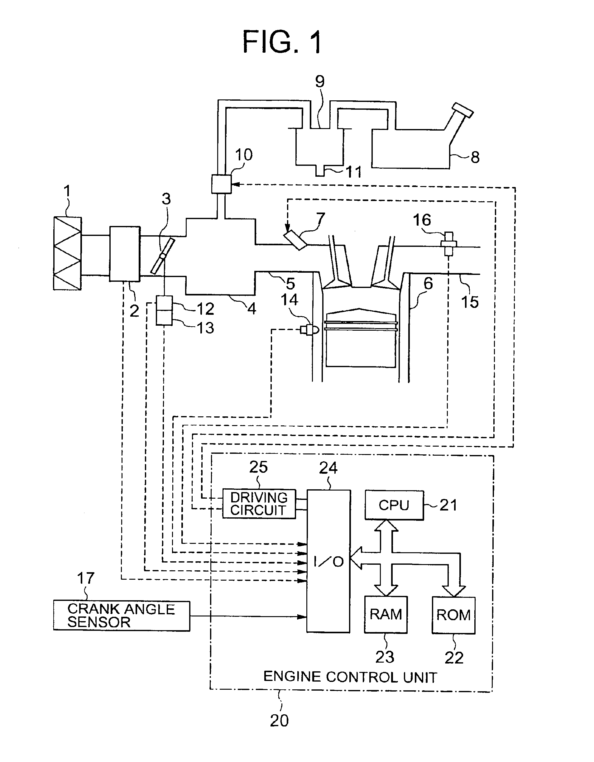
[0033]FIG. 1 is a functional block diagram showing generally and schematically a configuration of the air-fuel ratio control apparatus for an internal combustion engine according to a first embodiment of the present invention.

[0034]Referring to FIG. 1, intake air cleaned through an air cleaner 1 is fed to individual cylinders of the internal combustion engine 6 by way of an air flow sensor 2, a throttle valve 3, a surge tank 4 and an intake manifold or pipe 5. In that case, the flow rate or quantity Qa of the intake air is measured by the air flow sensor 2 while it is controlled by the throttle valve 3 in dependence on a load applied onto the engine 6.

[0035]On the other hand, fuel is injected into the intake pipe 5 through a fuel injector 7. Further, vaporized fuel (hereinafter also referred to as the fuel vapor) generated internally of a fuel tank 8 is adsorbed by a canister 9 containing activated carbon (or activated charcoal) therein. The fuel vapor adsorbed by the canister 9 is ...


PUM


Abstract

Air-fuel ratio control apparatus for an engine of automobile for controlling an air-fuel ratio to a desired value includes module (33) for computing a purge ratio (Pr) from a purge quantity (QPRG) and an engine operation state, module (35) for computing a purge air concentration (Pn) from the purge ratio (Pr) and an air-fuel ratio feedback correcting coefficient (CFB), module (36) for computing a purge air concentration correcting coefficient (CPRG) from the purge ratio and the purge air concentration, module (39) for computing a fuel injection quantity (Qf) supplied to the engine (6) from the purge air concentration correcting coefficient, and module (37) for detecting an accelerating state of the automobile. The purge air concentration correcting coefficient is reset to an initial value when the purge air concentration correcting coefficient is not greater than a predetermined value (indicating leanness) and when the acceleration is detected.

Description

BACKGROUND OF THE INVENTION[0001]1. Field of the Invention[0002]The present invention generally relates to an air-fuel ratio control apparatus for an internal combustion engine installed on an automobile or a motor vehicle. More particularly, the present invention is concerned with a technique for improving or enhancing an acceleration performance of the internal combustion engine equipped with the air-fuel ratio control apparatus which incorporates therein an air-fuel ratio feedback control function and a purge control function.[0003]2. Description of Related Art[0004]In general, the air-fuel ratio control apparatus for the internal combustion engine ordinarily incorporates the purge control function for causing a fuel vapor (i.e., vaporized fuel) originating in a fuel tank or the like to be adsorbed by activated carbon and purged to be introduced into an intake system of the engine as occasion arises. Further, the fuel injection apparatus of the internal combustion engine is equip...

Claims


Application Information

Patent Timeline
Patent Type & Authority Patents(United States)
IPC IPC(8): F02D41/00F02D41/10F02D41/14F02M25/08F02D41/02F02D43/00F02D45/00
CPCF02D41/0042F02D41/1454F02D41/10F02D41/0045F02D41/0032
Inventor HANAZAKI, RYOICHIKUNIHIRO, MITSUYASU
Owner MITSUBISHI ELECTRIC CORP
Why Eureka
Try Eureka