Cooler arrangement for agricultural implements

a technology for agricultural implements and coolers, which is applied in the direction of mechanical equipment, machines/engines, transportation and packaging, etc., can solve the problems of not being able to move quickly and easily, and affecting the operation of the equipment. , to achieve the effect of quick and easy movement and good accessibility

Inactive Publication Date: 2005-04-19
CASE CORPORATION +2
View PDF9 Cites 47 Cited by
  • Summary
  • Abstract
  • Description
  • Claims
  • Application Information

AI Technical Summary

Benefits of technology

[0011]It is an advantage of this invention that the front cooler can be moved upwardly and, if necessary, forwardly relative to the central cooler.
[0021]These and other objects, features and advantages are accomplished according to the instant invention by providing a cooler arrangement for agricultural implements, particularly for tractors that can be quickly and easily moved to permit access thereto for cleaning. The cooler block contains at least a front cooler, a central cooler, and a rear cooler. The rear cooler is attached at a fixed position on the frame of the agricultural tractor and the central cooler can be moved away from the rear cooler while the front cooler can also be moved away from the central cooler. The front cooler is suspended so that is can move sufficiently upwardly and, if necessary, also forwardly, that the central cooler can be swung away from the rear cooler unhindered to the side at about a right angle. The front cooler is joined to a tilting mechanism having a lever arm pointing in the direction of travel of the tractor.

Problems solved by technology

However, for agricultural implements this is not so easy to put into practice, as the space necessary for this type of arrangement is severely restricted by the wheels and the frame as well as the front lifting gear and possibly necessary ballast weights, so that always a part of the area to be cleaned remains inaccessible.
A disadvantage with this arrangement of coolers is that removal of the said coolers is relatively time-consuming.
By the incorporation of these coolers in guides for withdrawal towards the sides this procedure also requires physical effort as these guides are heavily soiled with the passage of time.
Furthermore, the coolers cannot be cleaned correctly, since the space for pulling them out to the side completely is simply not available.
With this arrangement of coolers the disadvantage is that through the said narrow gap, the inlet intercooler seen from above downwards can be cleaned with ever more difficulty, so that it does not attain maximum cooling performance.
Furthermore, with this arrangement of coolers it is impossible to fix a fourth cooler so that it too would be readily accessible for necessary cleaning.

Method used


Image

  • Cooler arrangement for agricultural implements
  • Cooler arrangement for agricultural implements
  • Cooler arrangement for agricultural implements

Examples


Embodiment Construction

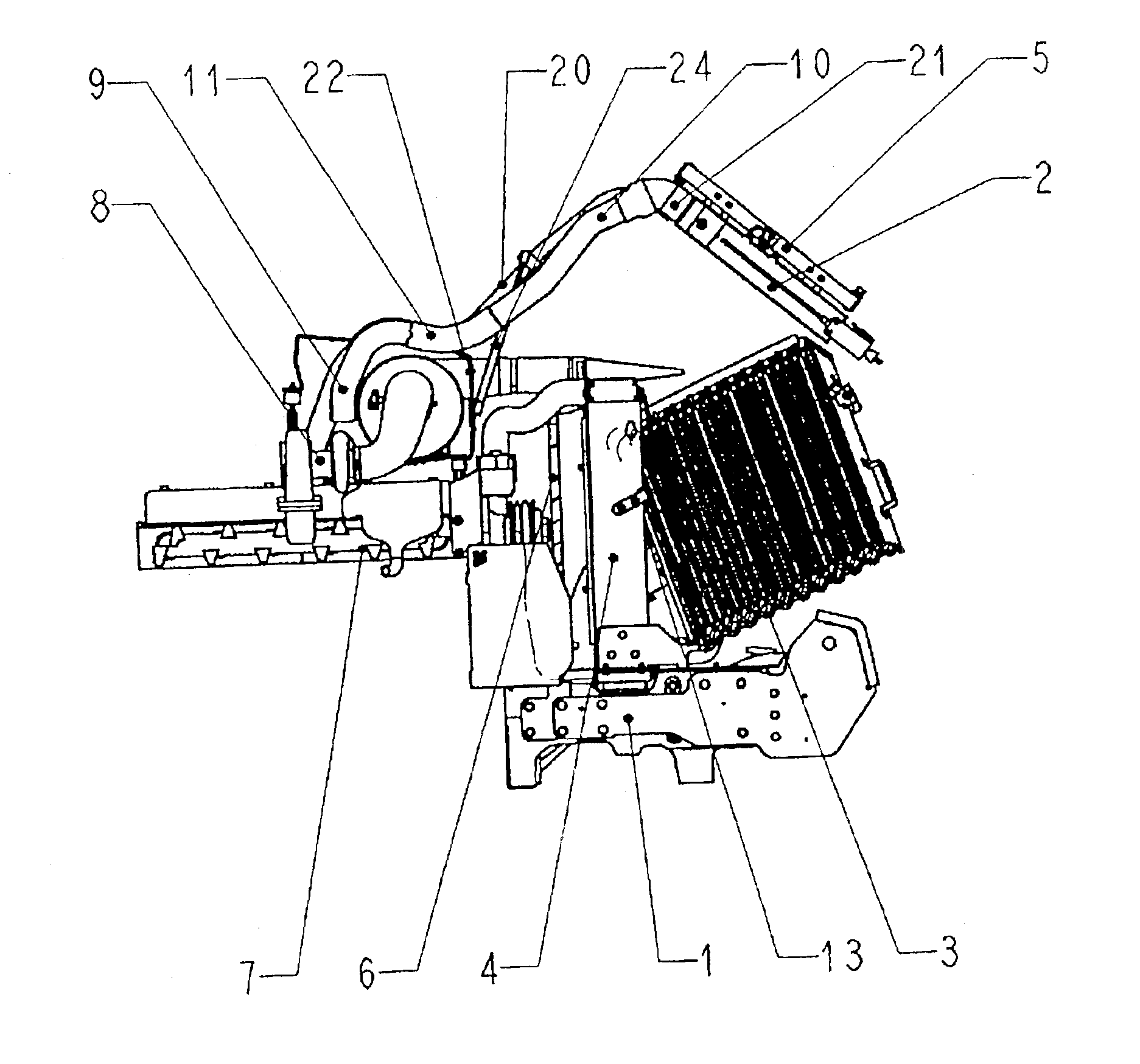
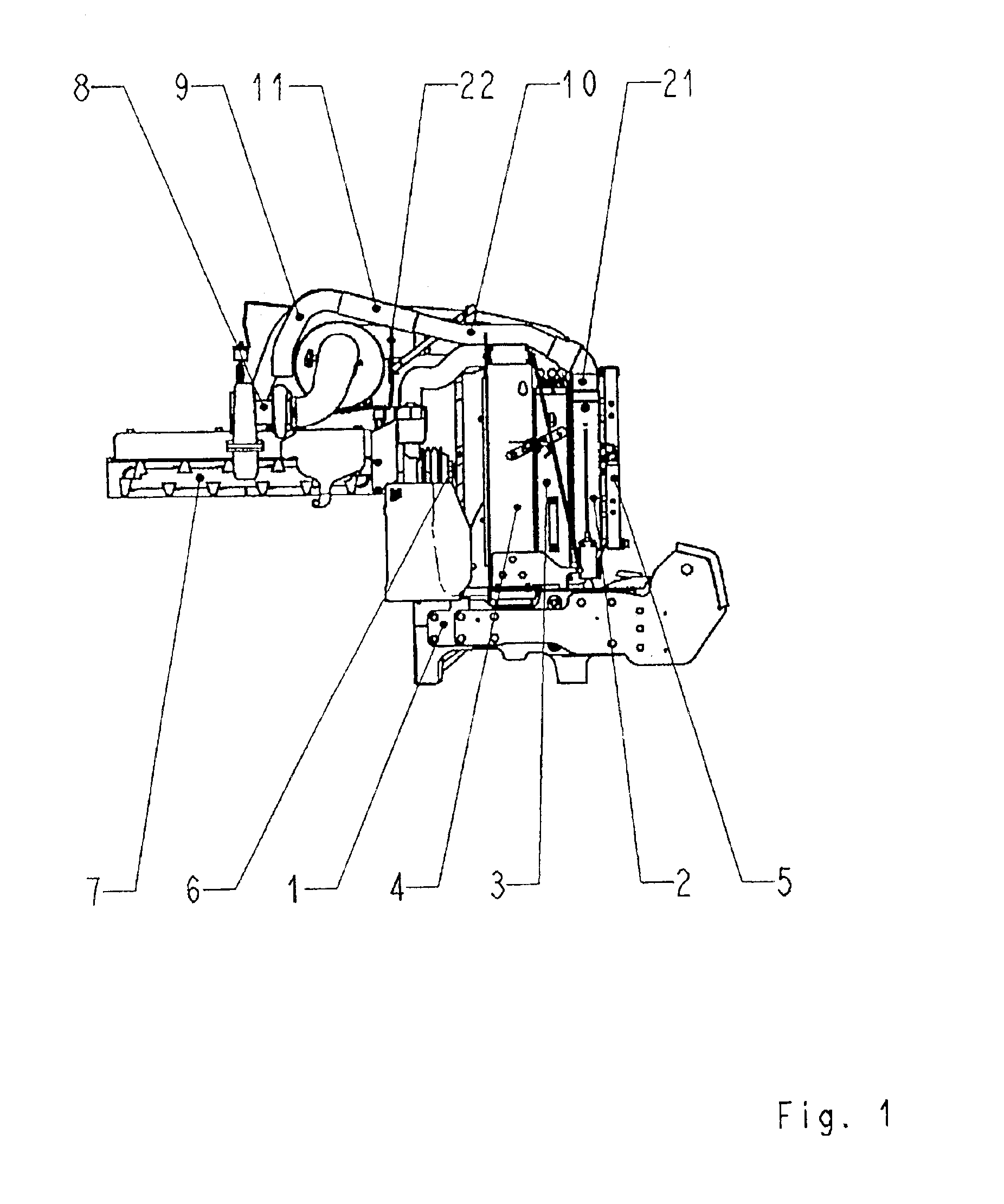
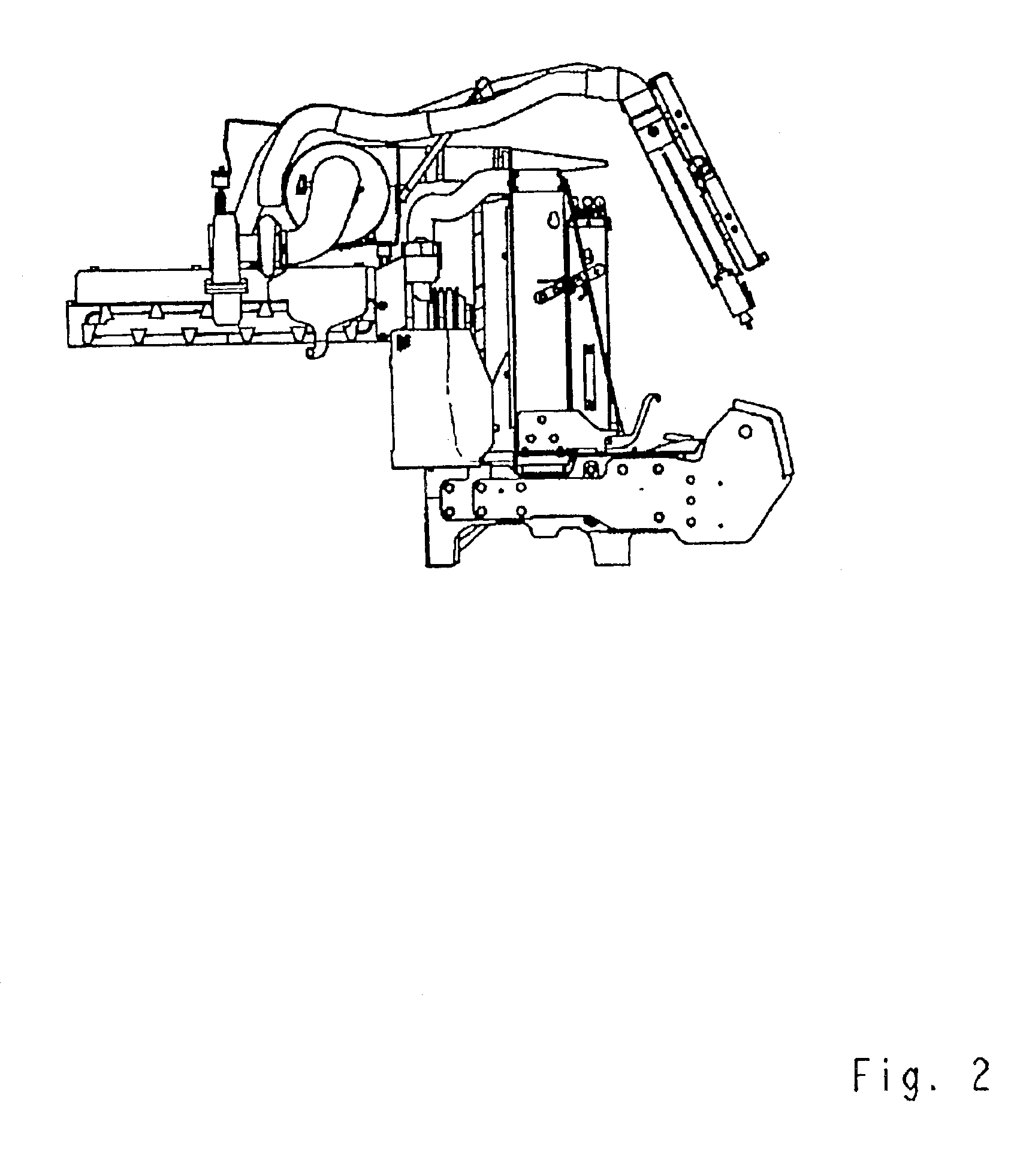
[0036]Referring to the drawings and particularly to FIG. 1, a schematic side view of a tractor from the right hand side as seen in the direction of travel shows the frame (1) on which the cooler arrangement is built. The cooler arrangement consists of a front cooler (2) designed as an inlet intercooler, a central cooler (3) designed as an oil cooler and a rear cooler (4) designed as a water cooler. On the front cooler (2) in addition a narrow air-conditioning cooler (5) is fixed on pivots, so that it can be swung sideways either to the left or to the right about a vertical axis as depicted in FIGS. 12 and 13, or about a horizontal axis upwards or downwards from this. A cooling fan (6) sucks a uniform stream of air through all the coolers (2), (3), (4) and (5) and is located behind the water cooler to be driven in a known manner from the engine (7) of the tractor. From this side also, the exhaust gas turbocharger (8) can be seen, to which a pipe (9) carrying charger air projecting up...


PUM


Abstract

A cooler arrangement for agricultural implements, particularly for tractors is quickly and easily moved to permit access thereto for cleaning. The cooler block contains at least a front cooler, a central cooler, and a rear cooler. The rear cooler is attached at a fixed position on the frame of the agricultural tractor and the central cooler can be moved away from the rear cooler while the front cooler can also be moved away from the central cooler. The front cooler is suspended so that is can move sufficiently upwardly and, if necessary, also forwardly, that the central cooler can be swung away from the rear cooler unhindered to the side at about a right angle. The front cooler is joined to a tilting mechanism having a lever arm pointing in the direction of travel of the tractor.

Description

BACKGROUND OF THE INVENTION[0001]The present invention relates a cooler arrangement for agricultural implements, especially for tractors and, more particularly, to a front cooler is suspended so that is can move away from the rear cooler.[0002]The cooler arrangement in powerful tractors is mostly laid out today, viewed in the direction of travel, so that the oil cooler is located in front of the water cooler and immediately in front of the oil cooler the inlet intercooler is located, if the cooling fan is arranged behind the water cooler. The air inlet and outlet areas of these coolers are of equal size, so that the cooling fan sucks a uniform stream of cooling air through all the coolers in the cited sequence. The cooler block thus constructed is located in the case of tractors behind the air inlet opening of the cooler hood, which for the purpose of maintenance and repairs can be swivelled upwards.[0003]Since agricultural implements are known to be found frequently in an environme...

Claims


Application Information

Patent Timeline
Patent Type & Authority Patents(United States)
IPC IPC(8): B60K11/04B60K11/02F01P11/12F01P11/00F01P11/06F01P3/18
CPCB60K11/04F01P11/12F01P3/18F01P2011/063
Inventor PFUSTERSCHMID, JOHANNHALLER, ROBERT
Owner CASE CORPORATION
Why Eureka
Try Eureka