Manual knife sharpener with angle control

Inactive Publication Date: 2005-04-19
EDGECRAFT
View PDF10 Cites 54 Cited by
  • Summary
  • Abstract
  • Description
  • Claims
  • Application Information

AI Technical Summary

Benefits of technology

[0007]Advantages of manual sharpeners as a class are their simplicity, portability and ease of use. The new and novel guide structure described here preserves these advantages while permitting control of the blade to be totally manual and where its control is enti

Problems solved by technology

A wide variety of manual knife sharpeners have been used for centuries, but most of these have been disappointing because they did not provide a precise means to control the sharpening angle.
A major disadvantage of using such clamping devices or carriers to control sharpening angle is the awkwardness and inconvenience of the

Method used


Image

  • Manual knife sharpener with angle control
  • Manual knife sharpener with angle control
  • Manual knife sharpener with angle control

Examples


Embodiment Construction

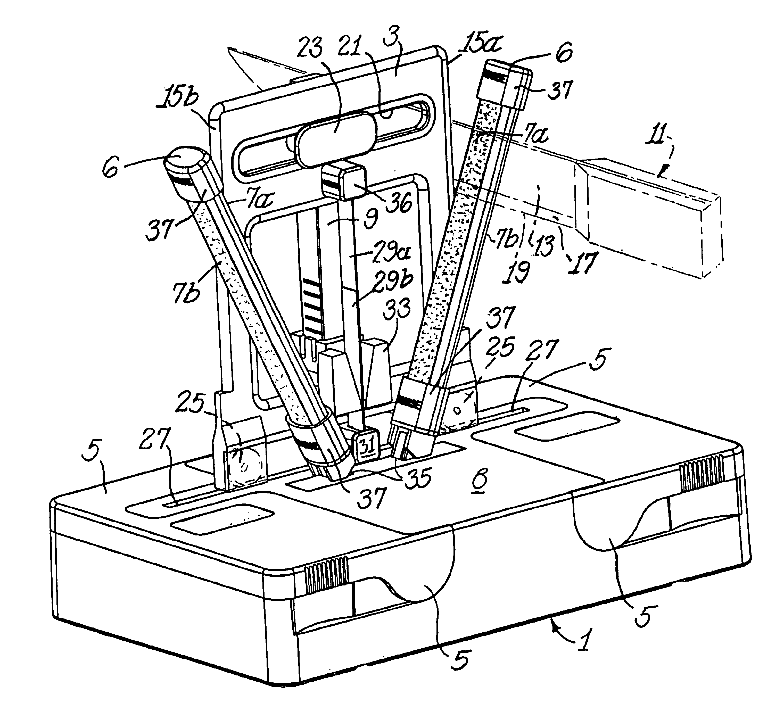
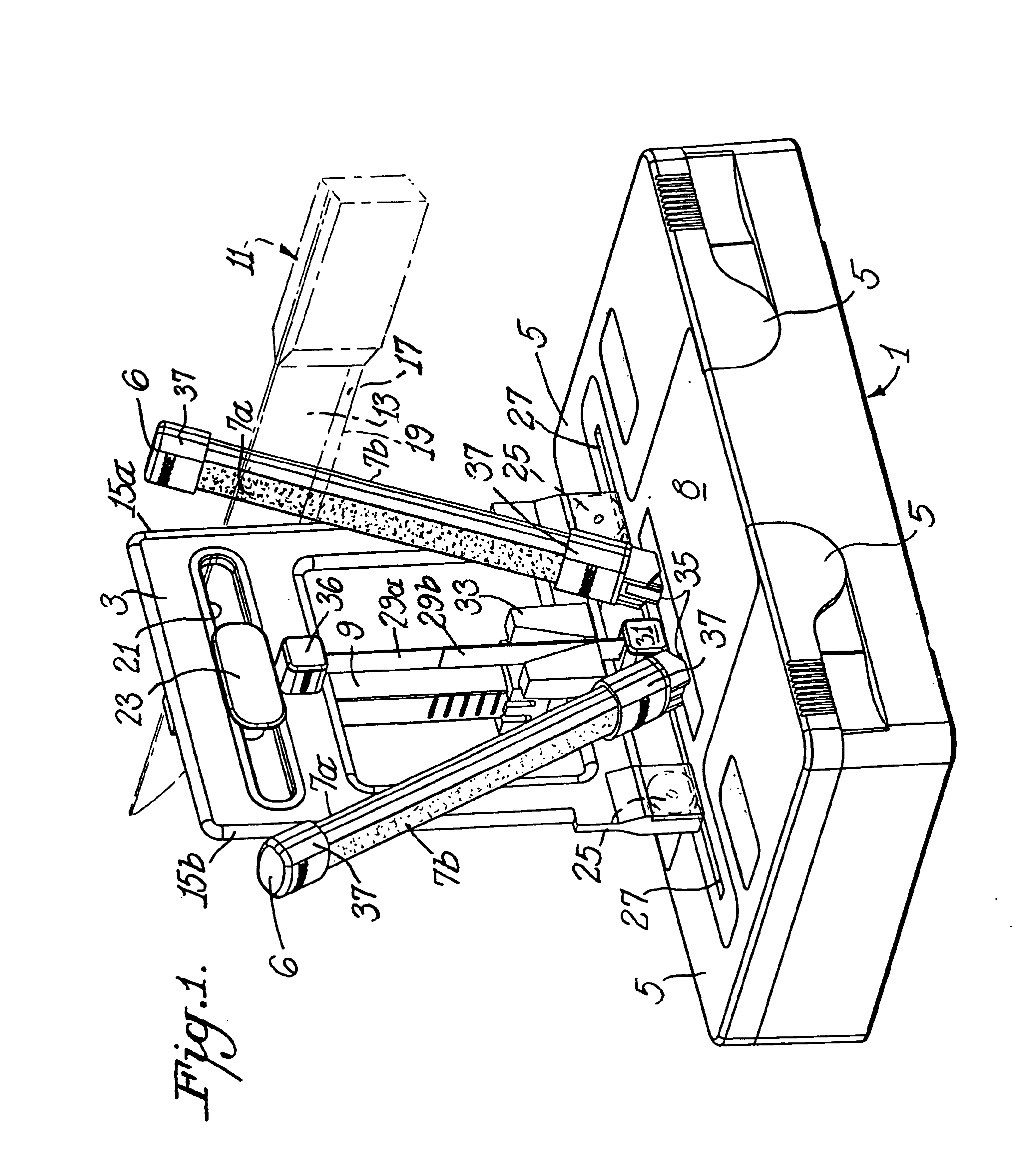
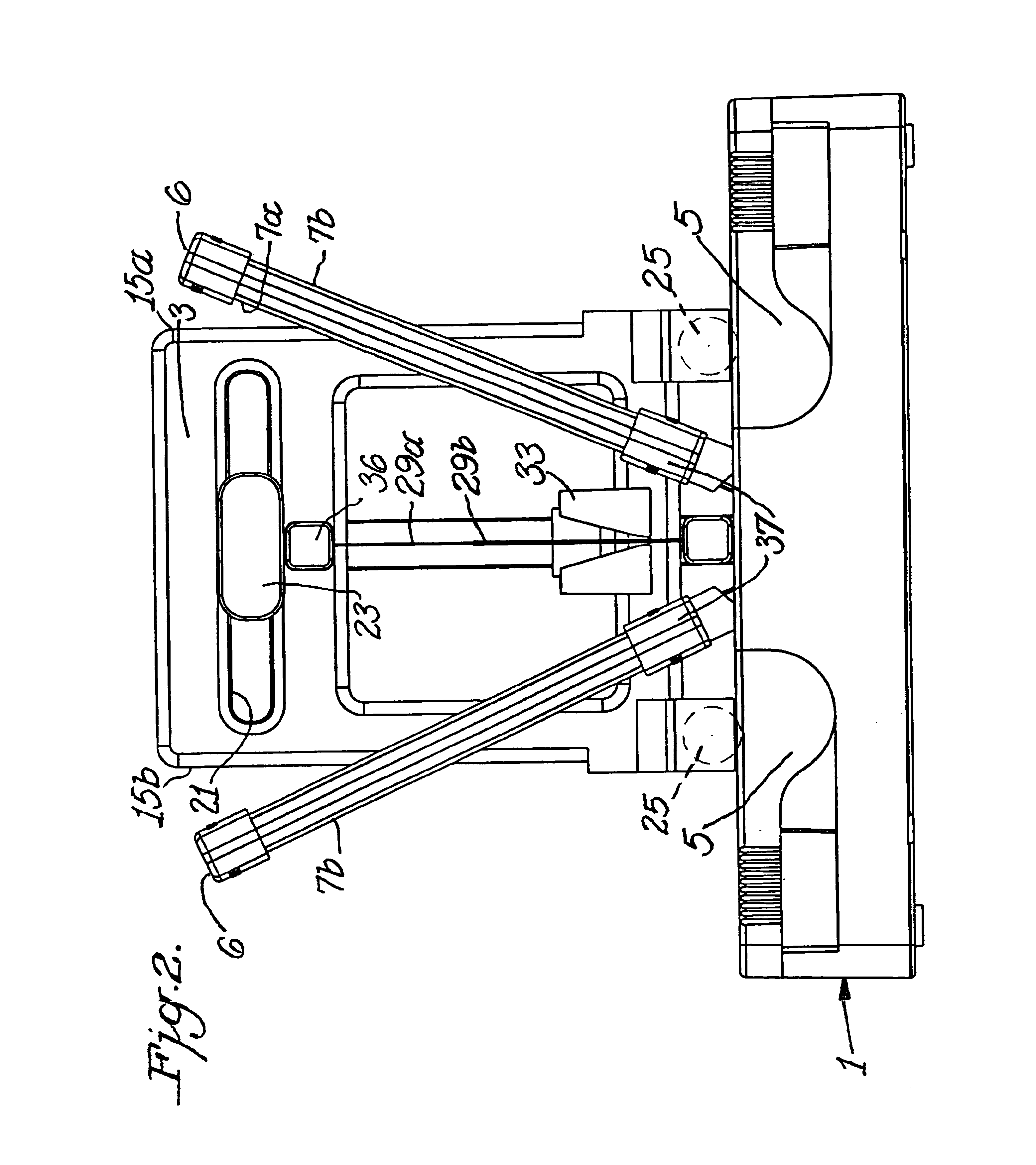
[0021]A sharpener 1 that incorporates the novel knife guiding principle of this invention is illustrated in FIGS. 1 and 2. A supporting structure 8 serves both to support the active components of the sharpener and to provide storage space in a single compartment for those active components within its underside when the sharpener is not being actively used.

[0022]Each of two inclined and removable abrasive coated structures 6 are double sided and have abrasives or abrasive coatings on their mutually facing abrasive surfaces 7a and their opposite sides 7b. The abrasives can be solid materials such as alumina, or silica, for example. Alternatively the abrasives can be coatings of small abrasive particles of these or other materials including diamonds for example on metallic or other substrate materials. The abrasive coated structures 6 are designed to permit a coarse grit abrasive surface on one side such as on 7a and fine grit abrasive on the other side 7b.

[0023]One facet along the kn...


PUM

PropertyMeasurementUnit
Weightaaaaaaaaaa
Forceaaaaaaaaaa
Angleaaaaaaaaaa

Abstract

A sharpener for blades comprises a physical structure supporting at least one abrasive surface. A displaceable guiding plate having an integral linear structural feature of the support is disposed toward one side of the abrasive surface. The linear structural feature provides sliding contact with a face of the blade to establish the relative angle of the plane of the edge facet of the blade with the plane of the abrasive surface at the point of mutual contact as the facet is guided into contact with the abrasive surface.

Description

CROSS REFERENCE TO RELATED APPLICATIONS[0001]This application is a continuation-in-part of application Ser. No. 10 / 023,190, filed Dec. 18, 2001 now U.S. Pat. No. 6,726,551, which is based on provisional application Ser. No. 60 / 260,980, filed Jan. 11, 2001.BACKGROUND OF THE INVENTION[0002]A wide variety of manual knife sharpeners have been used for centuries, but most of these have been disappointing because they did not provide a precise means to control the sharpening angle. The importance of angle control to the creation of ultra sharp knife edges is recognized in, for example, U.S. Pat. Nos. 5,390,431 and 4,627,194.[0003]Manual sharpeners have been described by others where control of the sharpening angle is obtained by use of clamping devices or blade carriers in which the blade is mounted in a mechanism and physically restrained so that the facet of the blade edge is restrained to remain parallel to the abrasive sharpening surface as the clamping device or carrier is moved in a...

Claims


Application Information

Patent Timeline
IPC IPC(8): B24D15/00B24D15/08
CPCB24D15/08
Inventor FRIEL, SR., DANIEL D.
Owner EDGECRAFT
Why Eureka
Try Eureka