Axial tube assembly for a motor

a technology of axial tube and motor, which is applied in the direction of bearing unit rigid support, liquid fuel engines, instruments, etc., can solve the problems of noise generation and uneven rotation, and achieve the effect of reliable positioning of the bearing of the motor

Inactive Publication Date: 2005-04-19
SUNONWEALTH ELECTRIC MACHINE IND
View PDF3 Cites 43 Cited by
  • Summary
  • Abstract
  • Description
  • Claims
  • Application Information

AI Technical Summary

Benefits of technology

[0008]A further object of the present invention is to provide an axial tube assembly for a motor for prolonging the life of the bearing of the motor.
[0009]Still another object of the present invention is to provide an axial tube assembly for a motor for improving rotational stability of the rotor of the motor.

Problems solved by technology

As a result, the rotational stability is adversely affected, resulting in imbalanced rotation and generation of noise.

Method used


Image

  • Axial tube assembly for a motor
  • Axial tube assembly for a motor
  • Axial tube assembly for a motor

Examples


first embodiment

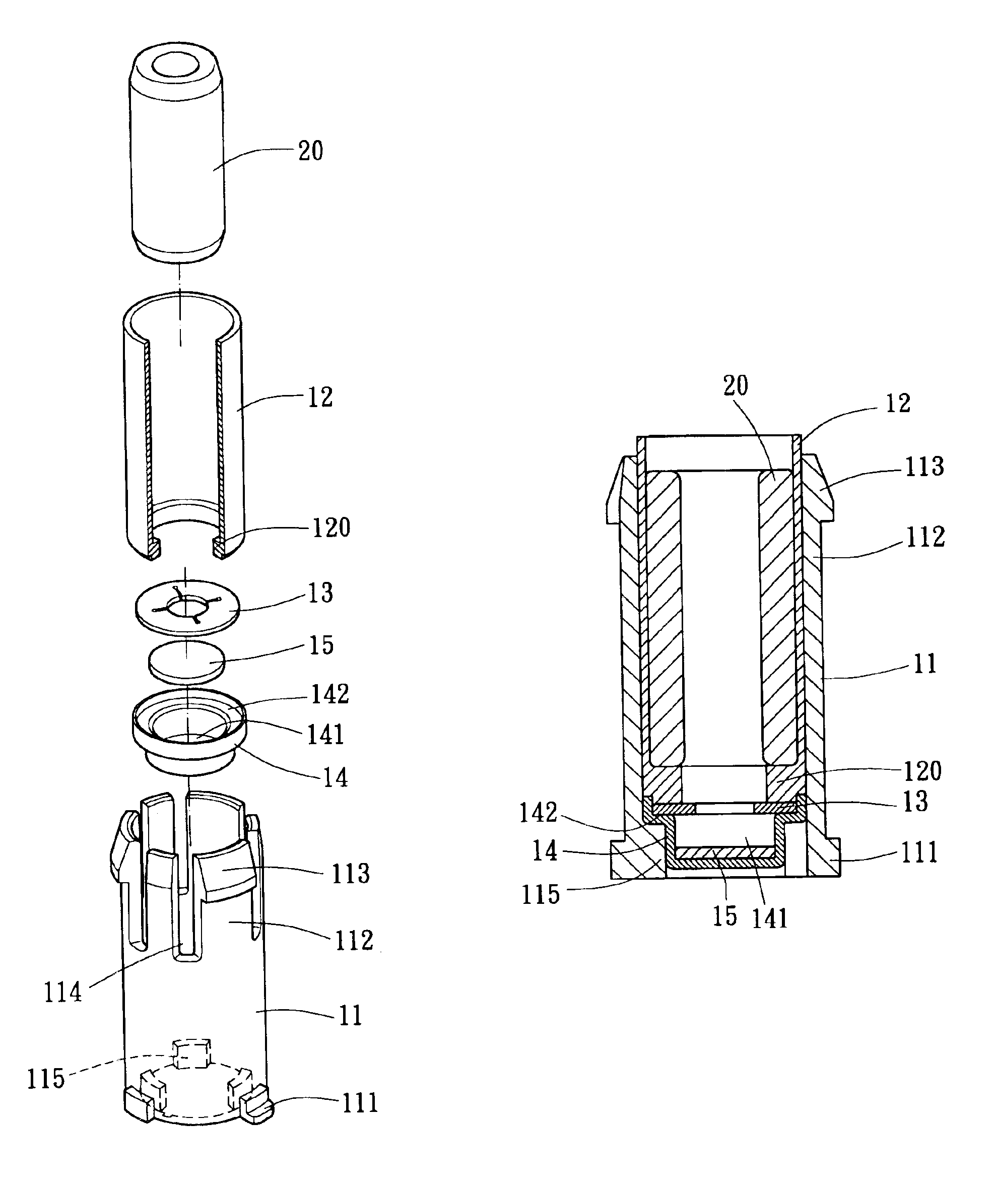
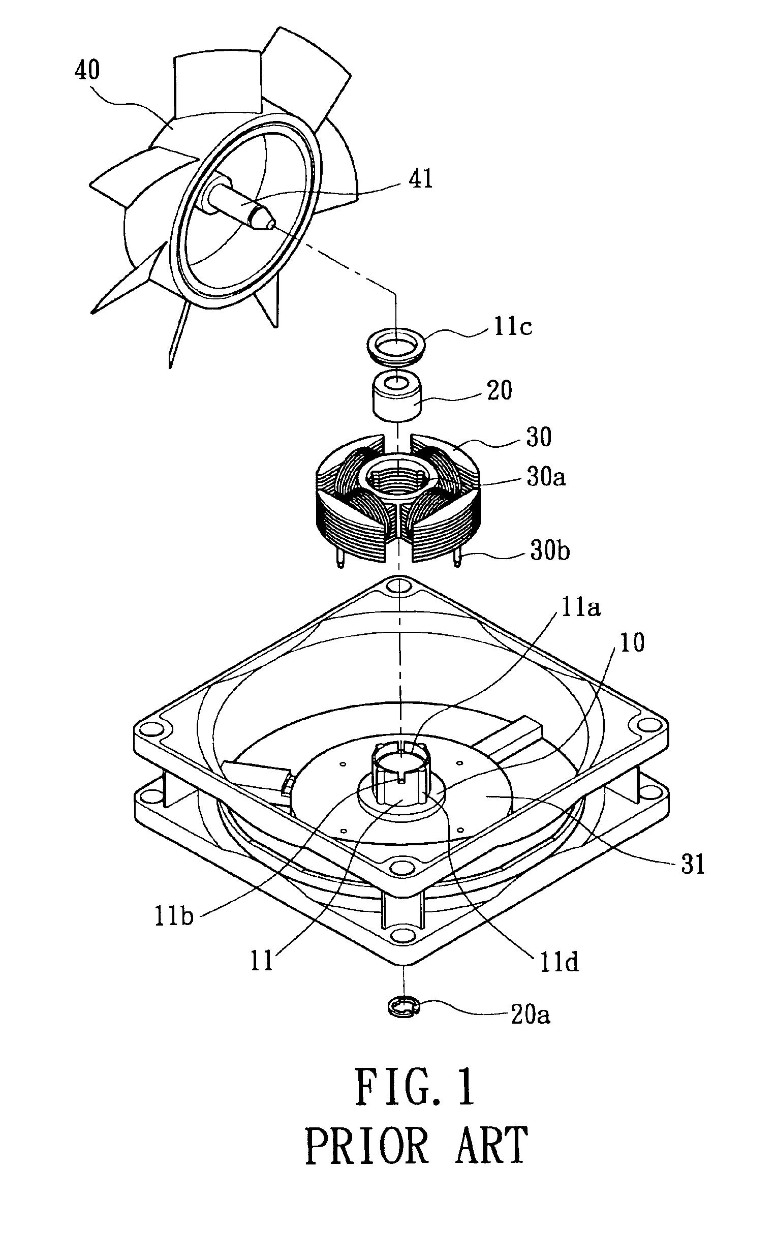
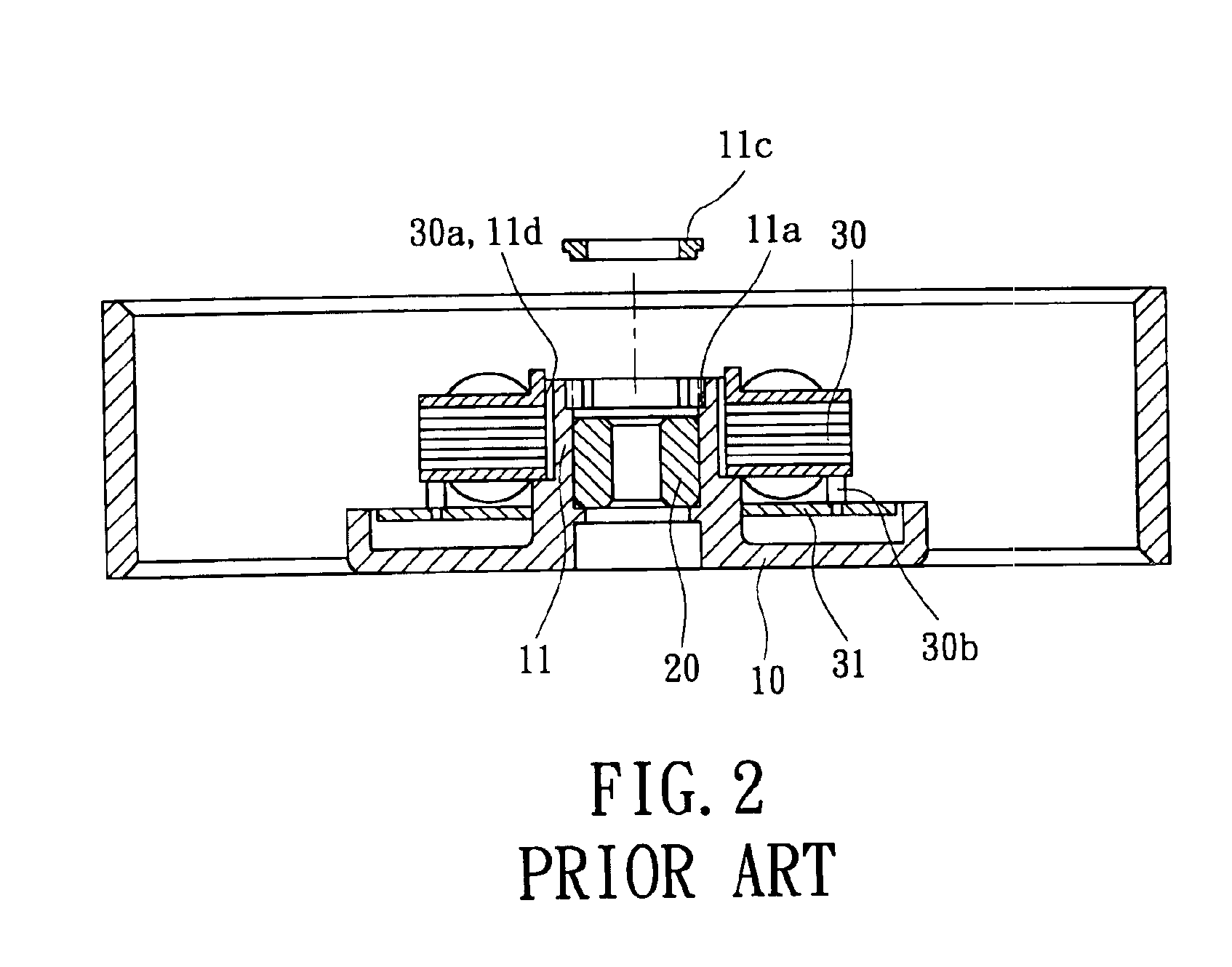
[0027]Referring to FIGS. 3 through 5, an axial tube assembly for a motor in accordance with the present invention includes an axial tube 11 and a sleeve 12. The axial tube 11 can be mounted to a casing 10 and engaged with a bearing 20, a stator 30, a circuit board 31, and a rotor 40, thereby forming a motor, as shown in FIG. 6.

[0028]The axial tube 11 is preferably made of a plastic material and includes plurality of engaging blocks 111 on a lower end of an outer periphery thereof. A plurality of protrusions 115 are formed on a lower end of an inner periphery of the axial tube 11. Preferably, the protrusions 115 are spaced by regular intervals and symmetrically disposed. Further, a plurality of longitudinal slits 114 are defined in an upper end of the axial tube 11, thereby forming a plurality of resilient tabs 112 on the upper end of the axial tube 11, with each resilient tab 112 having a hook 113 on an outer side thereof. The respective resilient tab 112 possesses required resilien...

third embodiment

[0037]FIGS. 11 and 12 illustrate the invention, wherein the inner flange 120 of the sleeve 12 is omitted to simplify the structure of the sleeve 12. As illustrated in FIG. 12, the positioning ring 13, the supporting member 14, and the abrasion-resisting plate 15 are reliably sandwiched between the bottom end (not labeled) of the sleeve 12 and the protrusions 115 of the axial tube 11 by means of choosing a bearing 20 with an appropriate specification.


PUM

PropertyMeasurementUnit
resilientaaaaaaaaaa
forcesaaaaaaaaaa
rotational stabilityaaaaaaaaaa

Abstract

An axial tube assembly for a motor includes an axial tube and a sleeve mounted in the axial tube. The axial tube is securely mounted to a casing, and a stator is mounted to the axial tube. When a bearing is mounted in the sleeve, the sleeve is tightly engaged with the axial tube such that the axial tube and the bearing exert forces to each other to thereby retain the axial tube and the bearing in place.

Description

BACKGROUND OF THE INVENTION[0001]1. Field of the Invention[0002]The present invention relates to an axial tube assembly for a motor. In particular, the present invention relates to an axial tube assembly for reliably positioning a bearing of a motor. The present invention also relates to a motor having such an axial tube assembly.[0003]2. Description of Related Art[0004]FIGS. 1 and 2 of the drawings illustrate a conventional motor including a casing 10, a bearing 20, a stator 30, a circuit board 31, and a rotor 40. The casing 10 includes an axial tube 11 integrally formed on a central portion of the casing 10. The axial tube 11 includes a stepped portion 11a on an inner periphery thereof and a plurality of longitudinal slits 11b in a top end thereof. The slits 11b allow the axial tube 11 to expand radially outward. After the bearing 20 is mounted into the axial tube 11, a retaining cap 11c is mounted to the stepped portion 11a to improve assembling reliability, and a shaft 41 of the...

Claims


Application Information

Patent Timeline
Patent Type & Authority Patents(United States)
IPC IPC(8): F16C35/00F16C35/02F04D29/60F04D29/04F04D29/64H02K7/08H02K5/167F04D29/057G11B19/20
CPCF04D29/057F04D29/646F16C35/02H02K5/1675H02K7/085G11B19/2009F16C2370/12
Inventor HORNG, ALEXHONG, YIN-RONGHONG, CHING-SHENG
Owner SUNONWEALTH ELECTRIC MACHINE IND
Why Eureka
Try Eureka