Exponential current generator and method

a generator and current technology, applied in the field of exponential current generators and methods, can solve the problems of power control problems, disadvantageous non-exponential relationship of the ratio,

Inactive Publication Date: 2005-04-19
QUALCOMM INC
View PDF16 Cites 11 Cited by
  • Summary
  • Abstract
  • Description
  • Claims
  • Application Information

AI Technical Summary

Benefits of technology

[0009]The invention includes an apparatus for generating a current pair, Ip, Im where the ratio of the pair is exponentially related to a control signal. In one embodiment of the present invention, a boost current, Iboost is added to a fixed current Ifixed to control the minimum or maximum value of either Ip or Im while keeping the ratio of Ip/Im exponentially related to the control signal. In a particular embodiment, Iboost is added so that Im is equal to or greater than a minimum value Ibleed. The apparatus includes a differential amplifier and a correction feedback circuit.
[0010]In one embodiment, the differential amplifier generates the current pair, Im, Ip, based on the control signal, the fixed current Ifixed, and the boost current Iboost. The correction feedback circuit is coupled to the differential amplifier and senses the level of Im. In accordance with this embodiment, the correction feedback circuit generates a boost current Iboost when Im is less than Ibleed so that Im will be greater than Ibleed and the ratio of Ip/Im will still be exponentially related to the control signal.
[0011]In a preferred embodiment, Iboost is proportional to a difference between Ibleed and Im when Im is less than Ibleed, otherwise Iboost is zero. The differential amplifier may include a current source that generates the fixed current Ifixed. In addition, the differential amplifier may further include a pair of BJTs, where the control signal is coupled to the bases of the BJTs

Problems solved by technology

This ratio is disadvantageously not exponentially related to the control signal Vcontrol.
Disadvantageously, this distortion causes the gain of a current amplifier employing the generator to become more linearly related than exponentially

Method used


Image

  • Exponential current generator and method
  • Exponential current generator and method
  • Exponential current generator and method

Examples


Embodiment Construction

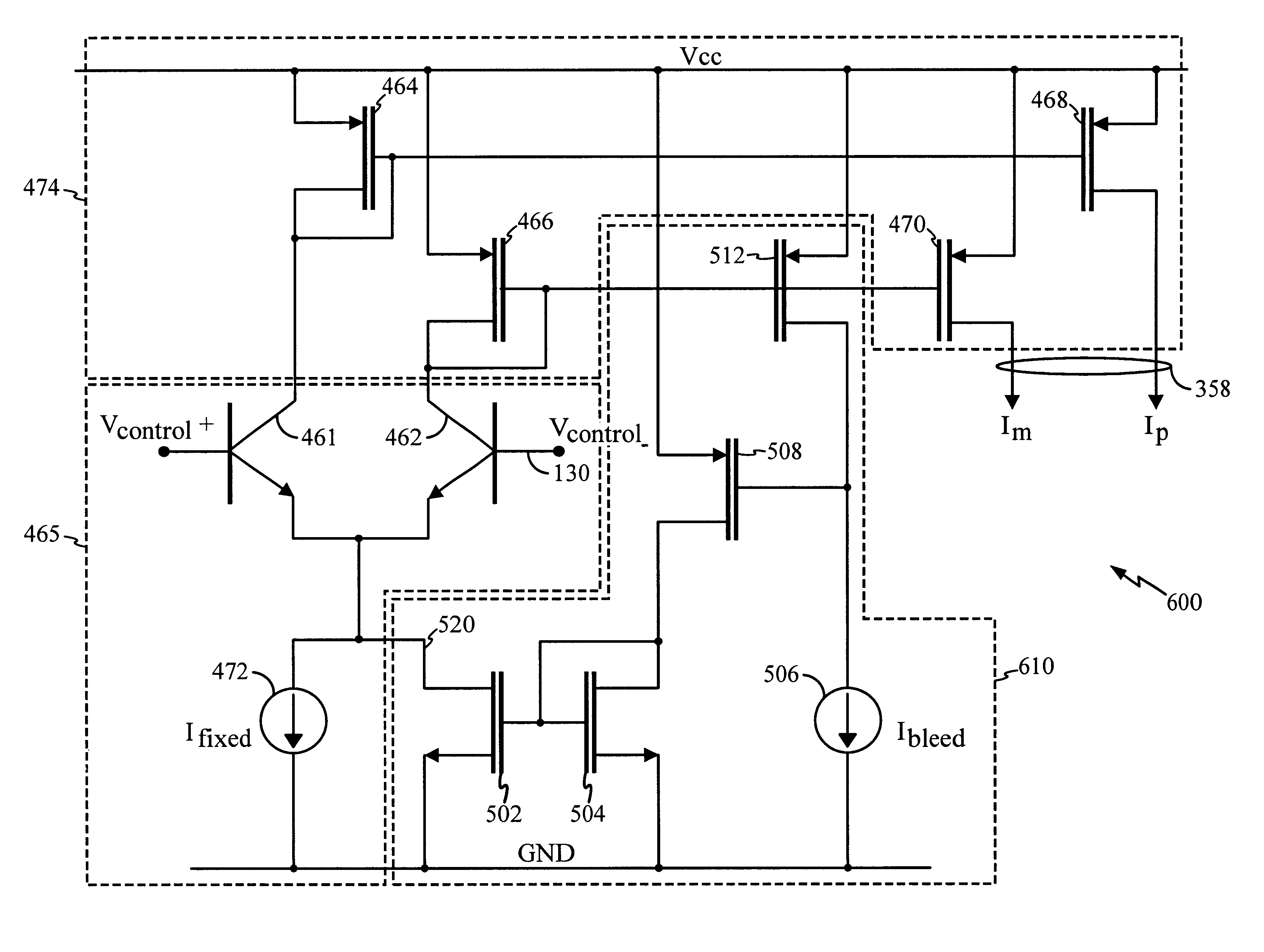
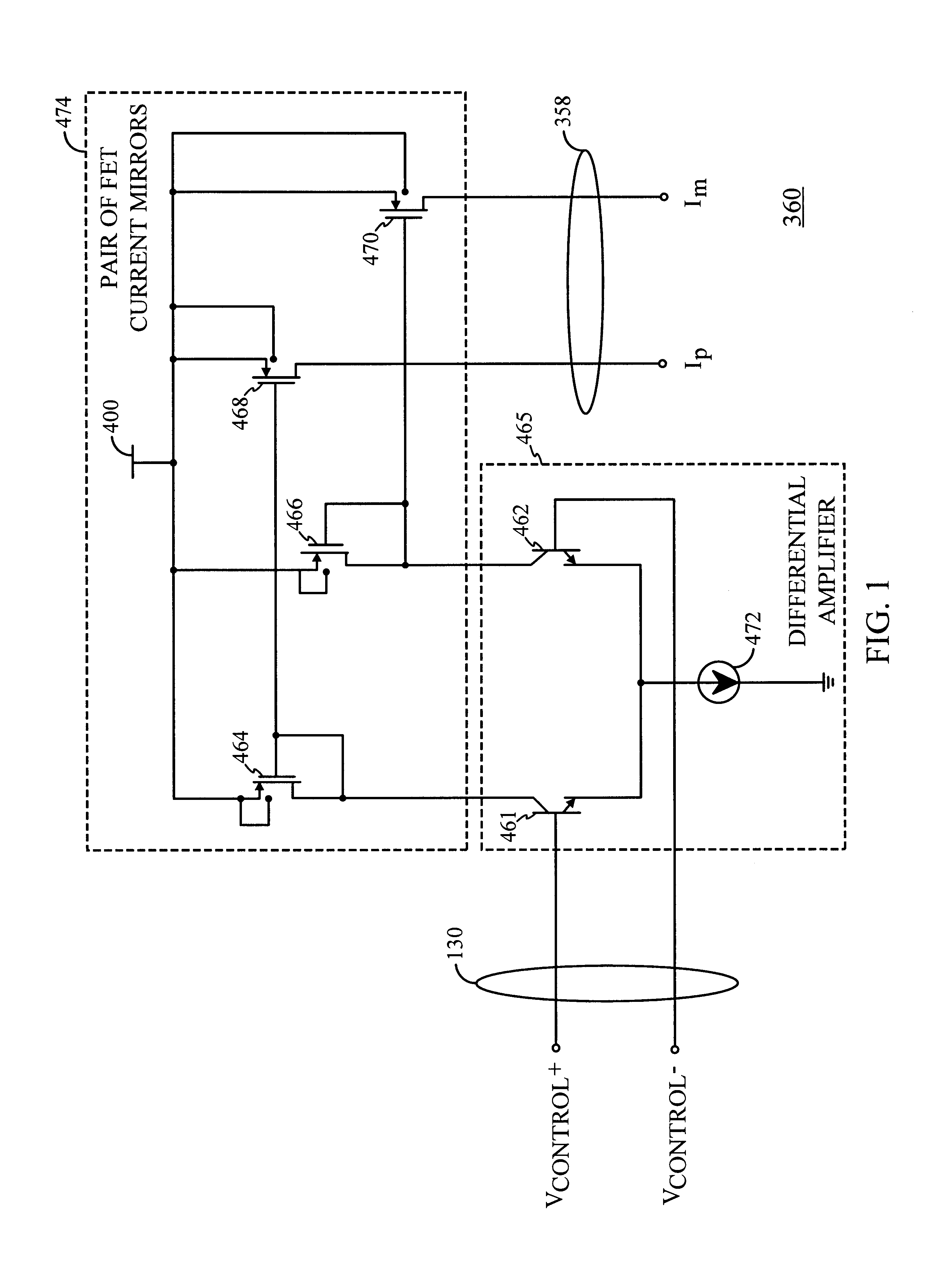
[0020]FIG. 1 shows an exponential function generator described in the related and co-pending application and is referred to hereafter as the exponential function generator 360. As shown in FIG. 1 and as described in the related application, the generator 360 primarily comprises a differential amplifier 465. The amplifier 465 generates a current pair Im, Ip at an output port 358 as a function of the differential value of a control signal, in this case a voltage control signal Vcontrol provided at an input port 130. As shown in FIG. 1, Vcontrol is coupled to the bases of Bipolar Junction Transistors (BJT) 461 and 462. The ratio of the collector currents of the BJTs 461 and 462 is exponentially related to the differential base voltage (Vcontrol) due to the known exponential input voltage-to-output current relationship of BJTs.

[0021]A pair of FET current mirrors 474 are used to copy the collector currents that are generated by the pair of BJTs 461, 462. In particular, the collector curr...


PUM


Abstract

An apparatus and method of generating a current pair Ip, Im where the ratio of the pair is exponentially related to a control signal, and where either Ip or Im is greater than or less than a minimum or maximum value includes a feedback correction circuit used to sense the value of Im or Ip. The correction circuit supplies a boost current Iboost when the sensed value of Ip or Im is less than or greater than the minimum or maximum value. Iboost is preferably maintained proportional to the difference of the desired value and Ip or Im.

Description

CROSS REFERENCE TO RELATED APPLICATIONS[0001]This application is related to commonly assigned U.S. Pat. No. 5,880,631 issued on Mar. 9, 1999 filed Jan. 27, 1997 entitled “High Dynamic Range Variable Gain Amplifier,” which is hereby incorporated by reference.BACKGROUND OF THE INVENTION[0002]I. Field of the Invention[0003]This invention relates to exponential current generators and methods, and more particularly to generators used in variable gain amplifiers (VGA).[0004]II. Description of the Related Art[0005]As noted in the co-pending and related application cited above, variable gain amplifiers (VGA) may be employed to amplify received signals and signals to be transmitted. The gain of the VGA is determined by a control signal where the gain of the VGA in some applications is ideally exponentially (or, “linear in dB”) related to the control signal. The VGA may have an input stage and one or more current amplifier stages coupled to the input stage. The input stage receives a voltage ...

Claims


Application Information

Patent Timeline
IPC IPC(8): H03G1/00H03F3/45G06G7/24H03G3/02
CPCH03F3/45085H03F3/45179H03G1/0023H03F2203/45471H03F2203/45658H03F2203/45454
Inventor WALKER, BRETT CHRISTOPHERGAZZERRO, PETER C.
Owner QUALCOMM INC
Why Eureka
Try Eureka