High frequency switch-mode power amplifier

a power amplifier and switch-mode technology, applied in power amplifiers, amplifiers, electric devices, etc., can solve the problems of reducing efficiency, increasing losses in power switches, and limited feedback which can be applied, and achieves the effect of increasing the apparent operating frequency of the system and more feedback

Inactive Publication Date: 2005-04-19
BRUEL & KJAER VTS
View PDF9 Cites 10 Cited by
  • Summary
  • Abstract
  • Description
  • Claims
  • Application Information

AI Technical Summary

Benefits of technology

[0018]The use of a plurality of power devices, operating an interlaced fashion, in order to increas

Problems solved by technology

The amount of feedback which can be applied however is limited by the switching frequency of the individual switching elements.
However, in the half-bridge topology, as the switchin

Method used


Image

  • High frequency switch-mode power amplifier
  • High frequency switch-mode power amplifier
  • High frequency switch-mode power amplifier

Examples


Embodiment Construction

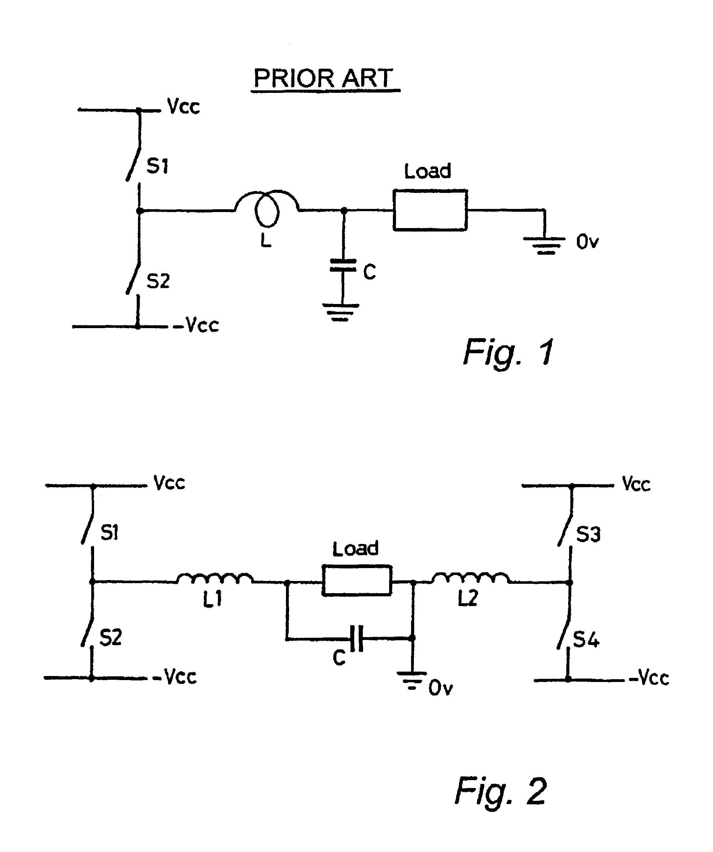
[0030]Referring to the drawings and initially to the prior art arrangements of FIGS. 1 and 2, a standard switching amplifier comprising a single half-bridge is shown in FIG. 1. The switching elements S1, S2 are operated at high frequency, for example, 150 kHz, each element being in the opposite switched state to the other. If the first switching element S1 is conducting or in a low impedance mode, that is, “ON”, then the second switching element S2 is not conducting or is in a high impedance state, that is “OFF”. In the particular application considered (driving an electromagnetic load), it is important that amplifier distortion is kept to a minimum. To achieve this, feedback is applied. The amount of feedback which can be applied is limited by the switching frequency of the switching elements. An increase in the switching frequency allows more feedback to be applied and thus decreases distortion. Unfortunately, high speed switching creates heating problems, increases losses in the ...


PUM


Abstract

A switch-mode power amplifier circuit using high power, low distortion waveforms is connected to an electromagnetic load to provide a high degree of control over the load. The circuit comprising a plurality of half-bridge networks having outputs combined at a summation point. The half-bridge networks are switched to provide power outputs sequenced to generate an interlaced output at the summation point which is operably connected to the load so that for a given switching frequency of the networks the operational frequency of the circuit is increased. The sequencing of the half-bridge outputs to generate an interlaced output facilitates the reduction of the switching frequency of individual switching components within the half-bridges while at least maintaining the overall operational frequency of the circuit. For N half-bridges operating at ƒkHz, the overall operational frequency of the circuit is NƒkHz. Alternatively, the switching frequency of individual switching elements of a system operating at ƒokHz may be reduced by a factor of N. A feedback signal generated across the load is included at the summation point and is optionally augmented to decrease distortion.

Description

FIELD OF THE INVENTION[0001]The present invention relates to power amplifiers adapted for driving electromagnetic loads including audio loudspeakers, motors and signal generating devices for vibration and acoustic testing. More particularly, the invention relates to switch-mode power amplifiers for use in vibration testing.BACKGROUND OF THE INVENTION[0002]Power amplifiers for use in driving, for example, electro-dynamic shakers must be capable of stable operation with a wide range of electrical loads, offer low distortion, make efficient use of electrical power, be compact in design and allow for computer control.[0003]The use of switch-mode power technology in such amplifiers provides many advantages over linear amplification techniques and are available presently in a range of 5 to 300 kVA. The use of switch-mode power technology dramatically improves amplifier efficiency over linear amplifiers, thus reducing power losses. This allows air cooling of semi-conductor heatsinks, as op...

Claims


Application Information

Patent Timeline
IPC IPC(8): H03F3/217H03F3/20
CPCH03F3/2178H03F3/2173
Inventor LEEDHAM, ROBERT
Owner BRUEL & KJAER VTS
Why Eureka
Try Eureka