Liquid crystal display apparatus and electronic device incorporating the same

a technology of liquid crystal display and electronic device, which is applied in the direction of identification means, instruments, optical light guides, etc., can solve the problems of reducing the display quality of apparatus incorporating half mirrors, requiring a complicated manufacturing process, and reducing the display quality of half mirrors. , to achieve the effect of reducing the generation of fringes, reducing the light reflected, and improving display quality

Inactive Publication Date: 2005-04-19
SHARP KK
View PDF14 Cites 5 Cited by
  • Summary
  • Abstract
  • Description
  • Claims
  • Application Information

AI Technical Summary

Benefits of technology

[0044]A liquid crystal display device according to the present invention includes an illumination section having a light source and an optical guide member, and a reflection type LCD having a display region including a plurality of pixels for performing a display function. The optical guide member includes first and second principal faces opposite to each other, and first and second end faces opposite to each other. The reflection type LCD is disposed on or above the first principal face of the optical guide member, so that the light from the light source enters the optical guide member at its first end face, exits the optical guide member at its first principal face so as to be incident on the reflection type LCD and reflected therefrom, reenters the optical guide member at its first principal face, and exits the optical guide member at its second principal face so as to reach the eyes of a viewer. As a result, the light from the light source can be effectively guided to the reflection type LCD even in a dark environment, so that a clear displayed image can be observed. In a relatively bright environment, a clear displayed image can be observed by utilizing ambient light, without utilizing the light from the light source.
[0062]Thus, the invention described herein makes possible the advantages of (1) providing a liquid crystal display apparatus with excellent portability and low power consumption, in which an illumination device is employed as a front light for a reflection type LCD, while preventing the generation of moire fringes and improving the display quality; and (2) providing an electronic device incorporating such a liquid crystal display apparatus.

Problems solved by technology

As a result, a reflection type liquid crystal display apparatus does not require a back light, and consumes relatively small power.
Furthermore, reflection type liquid crystal display apparatuses provide improved visibility in very bright conditions (e.g., indirect sunlight) where a transmission type liquid crystal display apparatus or any emission type display device would provide poor visibility.
However, a reflection type liquid crystal display apparatus has the following problems: since a reflection type display apparatus utilizes ambient light for display, its display luminance depends on the environment in which it is used.
This becomes particularly problematic for reflection type display apparatuses incorporating a color filter for color display functions because they require even more ambient light than monochrome display apparatuses.
However, half mirrors require a complicated manufacturing process.
Moreover, since the structure of a half mirror in itself does not make for highly efficient utilization of light, a semi-transmission type liquid crystal display apparatus incorporating a half mirror does not provide excellent display quality.
The pitch of the stripe lenses of the optical guide member and the period of the pixels of the transmission type LCD would normally interfere with each other to cause moire fringes.
However, by retaining an angle between the stripe lenses of the optical guide member and the pixels of the transmission type LCD, this technique sufficiently shortens the period of the moire fringes to prevent the viewer from perceiving them.
However, various problems may occur when any one of the above-described conventional illumination devices is employed as an illumination device (front light) for a reflection type LCD, as described below.
First, the illumination device disclosed in Japanese Utility Model Registration No. 3003427 is designed to illuminate objects such as drawings, pictures, or printed materials, which are usually unharmed by any moire patterns (moire fringes) emerging due to light interference.
If this illumination device is employed as a front light of a reflection type LCD, light interference may occur between the optical guide member and the regular array of pixels of the reflection type LCD, thereby causing moire fringes.
As a result, the display quality may greatly deteriorate.
Furthermore, while disclosing a technique of leading light onto the object to be illuminated, the 3003427 publication fails to disclose a light controlling portion having any specific shape or structure.
Therefore, using either one of the back lights disclosed in Japanese Laid-Open Publication Nos. 6-123884 and 8-68997 as a front light for a reflection type LCD cannot effectively prevent the generation of moire fringes.

Method used


Image

  • Liquid crystal display apparatus and electronic device incorporating the same
  • Liquid crystal display apparatus and electronic device incorporating the same
  • Liquid crystal display apparatus and electronic device incorporating the same

Examples


example 1

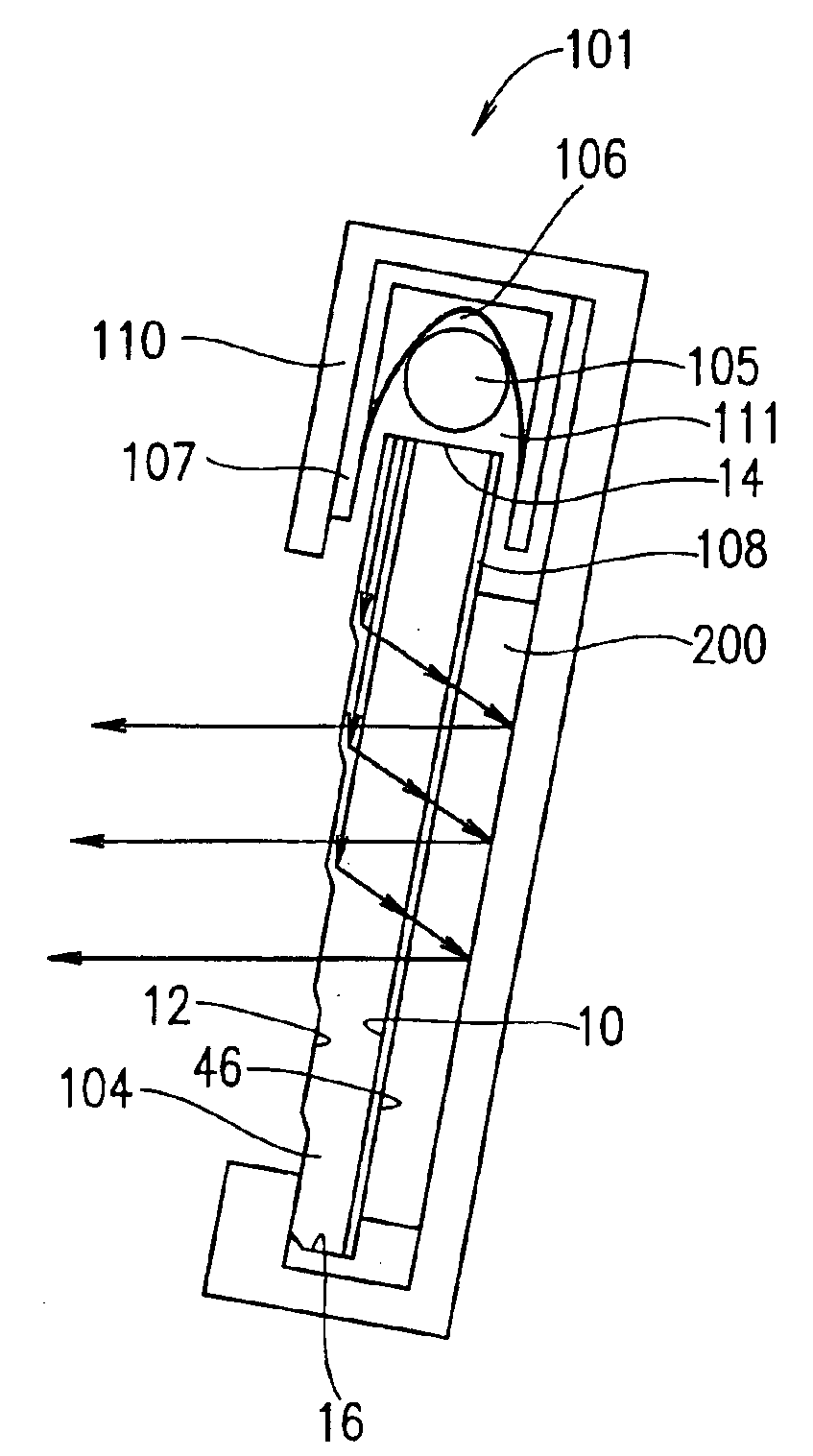
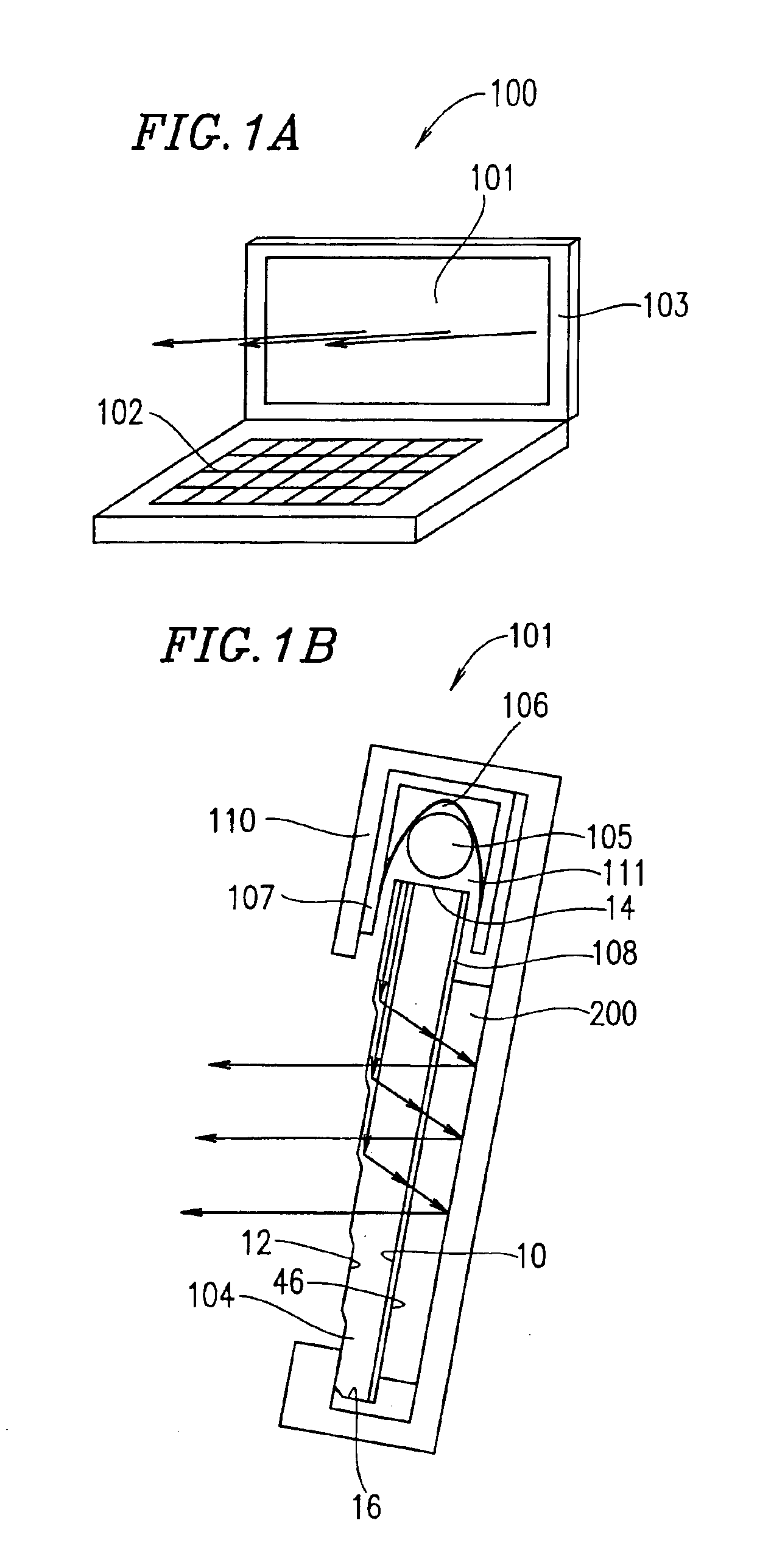
[0083]Example 1 of the present invention will be described with reference to FIGS. 1A, 1B to 7 and FIGS. 11 to 15. An electronic device 100 of Example 1 shown in FIG. 1A, which may be a portable information device or the like, includes a liquid crystal display apparatus 101 and an operation section 102.

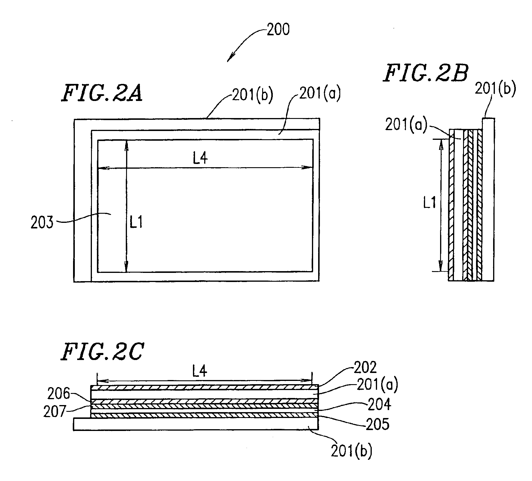
[0084]The liquid crystal display apparatus 101 includes an illumination section and a reflection type LCD 200 (FIGS. 2A to 2C). The illumination section includes a light source 105 and an optical guide member 104. The reflection type LCD 200 includes a display region including a plurality of pixels for performing a display function. The reflection type LCD 200 is disposed on or above a first principal face 10 of the optical guide member 104 included in the illumination section. Light from the light source 105 enters the optical guide member 104 through a first end face 14 of the optical guide member 104, as indicated by the arrows in FIG. 1B, and goes out at the first principal face 1...

example 2

[0125]Hereinafter, Example 2 of the present invention will be described with reference to FIGS. 8A to 10. An electronic device 700 of Example 2 (shown in FIG. 8A), which may be, for example, a portable electronic information device, includes a liquid crystal display apparatus 701. The liquid crystal display apparatus 701 may double as an operation section. The liquid crystal display apparatus 701 has a fundamental structure similar to that of the liquid crystal display device 101 of Example 1 (FIGS. 1A and 1B) except that, as shown in FIGS. 8A and 8B, the operation section, an illumination section, and a display screen according to the present example are constructed in an integral manner. Moreover, an optical guide member employed in the illumination section according to the present example is configured as described below, and a light source is located in a lower direction of the display region. The portable electronic information device illustrated in the present example employs ...


PUM

PropertyMeasurementUnit
angleaaaaaaaaaa
angleaaaaaaaaaa
angleaaaaaaaaaa

Abstract

A liquid crystal display apparatus includes: an illumination section having a light source and an optical guide member, and a reflection type LCD having a display region including a plurality of pixels for performing a display function, the optical guide member having first and second principal faces opposite to each other and first and second end faces opposite to each other. The reflection type LCD is disposed on or above the first principal face of the optical guide member. Light from the light source enters the optical guide member at the first end face, exits the optical guide member at the first principal face so as to be incident on the reflection type LCD and reflected therefrom, reenters the optical guide member at the first principal face, and exits the optical guide member at the second principal face toward a viewer.

Description

[0001]This application is a Divisional of Application Ser. No. 09 / 292,595, filed on Apr. 16, 1999 now U.S. Pat. No. 6,628,352, the entire contents of which are hereby incorporated by reference and for which priority is claimed under 35 U.S.C. § 120; and this application claims priority of Application Nos. 10-107410 and 10-365863 filed in Japan on Apr. 17, 1998 and Dec. 24, 1998, respectively, under 35 U.S.C. § 119.BACKGROUND OF THE INVENTION[0002]1. Field of the Invention[0003]The present invention relates to a liquid crystal display apparatus, more particularly to a front lit LCD apparatus, and a portable electronic device incorporating such a liquid crystal display apparatus.[0004]2. Description of the Related Art[0005]Liquid crystal display apparatuses display characters and / or images by adjusting the amount of transmitted portions of light from a light source. The liquid crystal itself does not emit light, unlike CRT (cathode ray tube) devices, PDP (plasma display) devices, and ...

Claims


Application Information

Patent Timeline
Patent Type & Authority Patents(United States)
IPC IPC(8): F21V8/00G02F1/1335G02F1/13G09F9/00G02B6/00G02F1/13357
CPCG02F1/133615G02B6/0048G02B6/0031G02F2001/133616G02F1/133616
Inventor SUMIDA, YUKIHIROMASUDA, TAKESHIEBI, TSUYOSHI
Owner SHARP KK
Why Eureka
Try Eureka