Method and system for interference lithography utilizing phase-locked scanning beams

Inactive Publication Date: 2005-04-19
MASSACHUSETTS INST OF TECH
View PDF32 Cites 198 Cited by
  • Summary
  • Abstract
  • Description
  • Claims
  • Application Information

AI Technical Summary

Benefits of technology

[0013]The invention provides a lithographic method and system of scanning beam interference lithography (SBIL). In the most general embodiment, this method and system utilizes matched pairs of coherent, phase-locked, overlapped writing beams incident on a substrate, which is coated with a photo-definable layer such as a lithographic resist. Alternatively, substrates incorporating regions of photosensitive material, such as sheets of lithium niobate, or optical fibers with SiGe oxide cores, may be used. The writing beam pairs are generated such that a carefully-controlled phase relationship exists between left and right beam pair halves, and between all beam pairs, which results in coherent interference and thus the generation of periodic patterns in the area of overlap (the “image”). The writing beams are typically much smaller in diameter than the substrate. Any number of overlapping beam pairs may be used, wherein the overlap region of all beam pairs on the substrate coincide. The substrate is chucked to a commercial, high-precision, three-axis (x-motion, y-motion, γ-rotation) motion stage, which is controlled by servo motors, a stage-position sensor such as a laser interferometer or optical encoder, a substrate surface z-height sensor, and control electronics. As the substrate is scanned by the x-y stage, the angles, phases, and amplitudes of the writing beams are controlled in a prescribed way to inscribe useful precision periodic patterns on the substrate.

Problems solved by technology

The writing beam pairs are generated such that a carefully-controlled phase relationship exists between left and right beam pair halves, and between all beam pairs, which results in coherent interference and thus the generation of periodic patterns in the area of overlap (the “image”).

Method used


Image

  • Method and system for interference lithography utilizing phase-locked scanning beams
  • Method and system for interference lithography utilizing phase-locked scanning beams
  • Method and system for interference lithography utilizing phase-locked scanning beams

Examples


Embodiment Construction

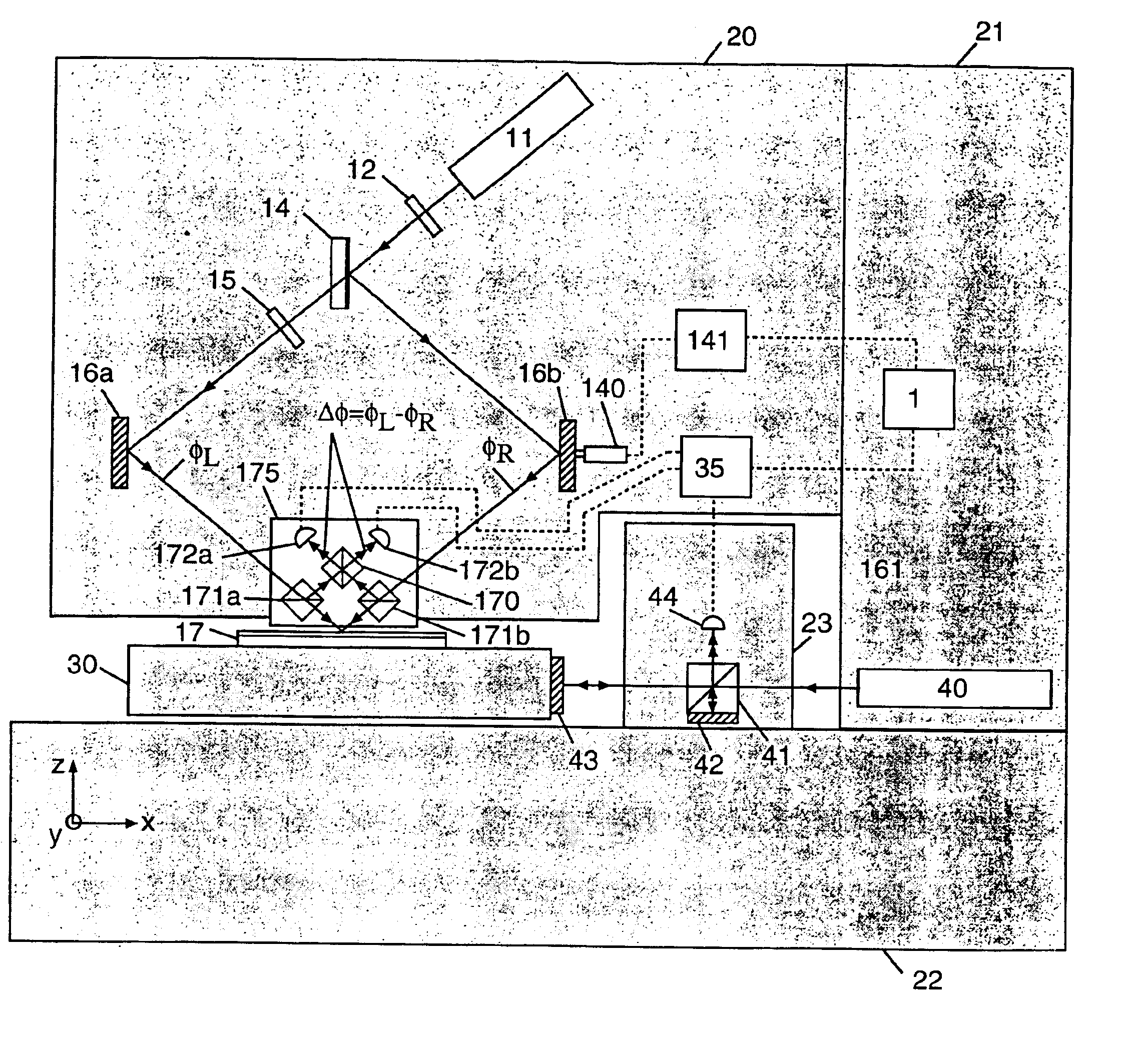
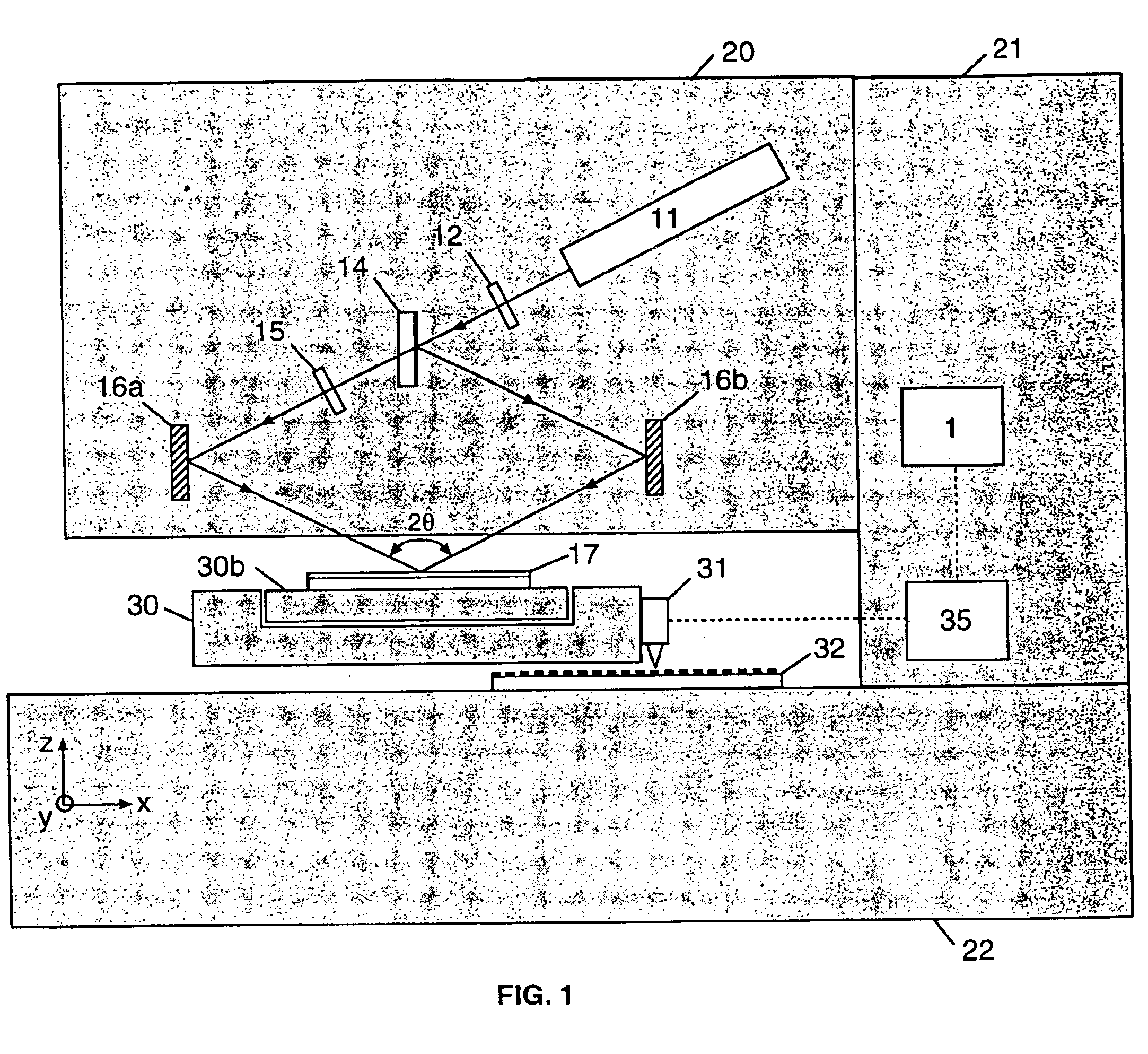
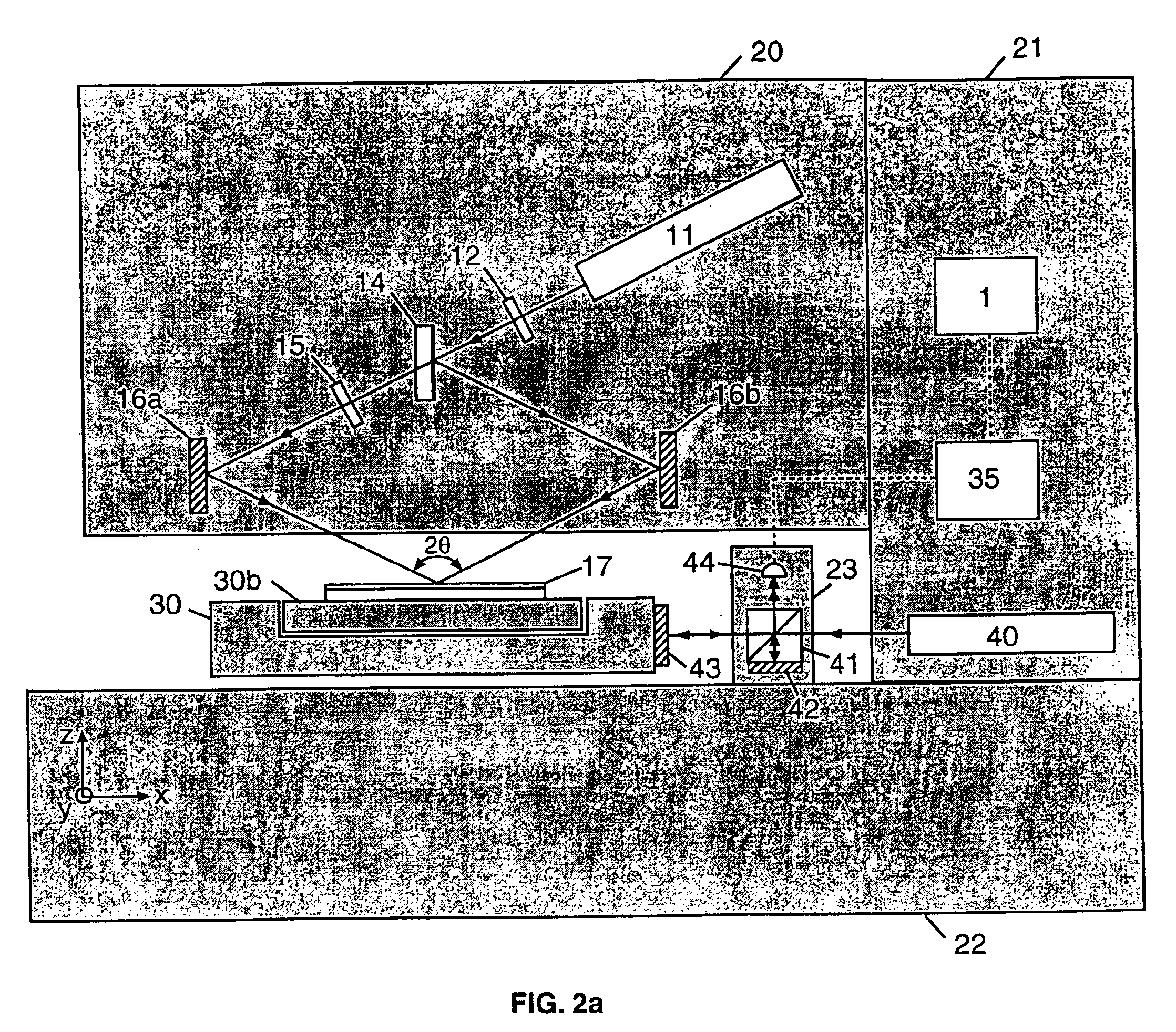
[0145]With reference now to the drawings and more particularly. FIG. 1 thereof, there is shown a pictorial representation of a scanning-beam interference lithography (SBIL) system in accordance with the invention.

[0146]A laser 11, of wavelength λ such as an argon-ion laser operating at the UW wavelength of λ=351 nm, emits a narrow beam that strikes shutter / attenuator 12. Shutter / attenuator 12 can be controlled electronically to commence the operation of SBIL by directing a portion of the beam to the remainder of the apparatus, comprising an interferometer. The interferometer, called the writing interferometer, comprises a dielectric beamsplitter 14 which creates two beams, a variable attenuator 15 for adjusting the irradiance of one of the beams until both match, and mirrors 16 for redirecting the beams onto substrate 17. Alternatively, a cube beamsplitter, or transmission or reflection grating beamsplitter, may be substituted for dielectric beamsplitter 14. The split beams are adju...


PUM

PropertyMeasurementUnit
wavelengthaaaaaaaaaa
diameteraaaaaaaaaa
angleaaaaaaaaaa

Abstract

A method and system of interference lithography (also known as interferometric lithography or holographic lithography) which utilizes phase-locked, scanning beams (so-called scanning beam interference lithography, or SBIL). The invention utilizes a high-precision stage that moves a substrate under overlapped and interfering pairs of coherent beams. The overlapped beams interfere, generating fringes, which form a pattern “brush” for subsequent writing of periodic and quasi-periodic patterns on the substrate. The phase of the fringes in the overlapped region is phase-locked to the motion of the precision stage. The invention includes methods for forming, overlapping, and phase-locking interfering pairs of beams on a variety of substrates; methods for measuring and controlling the period, phase, and angular orientation of fringes generated by the overlapping beams; and methods for measuring and controlling the effects of stage mechanical and thermal drift and other disturbances during the writing process.

Description

PRIORITY INFORMATION[0001]This application claims priority from provisional application Ser. No. 60 / 164,655 filed Nov. 10, 1999.GOVERNMENT SPONSORSHIP INFORMATION[0002]The government has rights to this invention pursuant to contract number NAG5-5105 awarded by the National Aeronautics and Space Administration, and contract number DAAG55 -98-1-0130 awarded by the Defense Advanced Projects Research Administration.BACKGROUND OF THE INVENTION[0003]1. Field of the Invention[0004]The invention relates to interference lithography (IL), also known as interferometric lithography or holographic lithography, a method wherein periodic or quasi-periodic patterns are exposed into a photosensitive material (in thin-film form, usually called a resist), by overlapping pairs of phase-locked beams from a laser or other intense source of radiation. In general, a beam, such as emitted from a laser, is split into pairs of beams, which are then directed to recombine at a resist-coated substrate. At the in...

Claims


Application Information

Patent Timeline
Patent Type & Authority Patents(United States)
IPC IPC(8): G03F7/20G03H1/04
CPCG03F7/70383G03F7/70408G03H2225/21G03H2001/0482G03H2222/36G03H1/0486
Inventor SCHATTENBURG, MARKEVERETT, PATRICK N.
Owner MASSACHUSETTS INST OF TECH
Why Eureka
Try Eureka