
Apparatus and method for sequencing memory operations in an asynchronous switch fabric

a technology of asynchronous switch fabric and apparatus, which is applied in the direction of pulse technique, data switching network, instruments, etc., can solve the problems of limiting the achievable communication rate, placing considerable electrical load on the wires in the bus, and slow communication paths in comparison with other logical structures

Inactive Publication Date: 2005-04-19
ORACLE INT CORP
View PDF3 Cites 23 Cited by
  • Summary
  • Abstract
  • Description
  • Claims
  • Application Information

AI Technical Summary

Benefits of technology

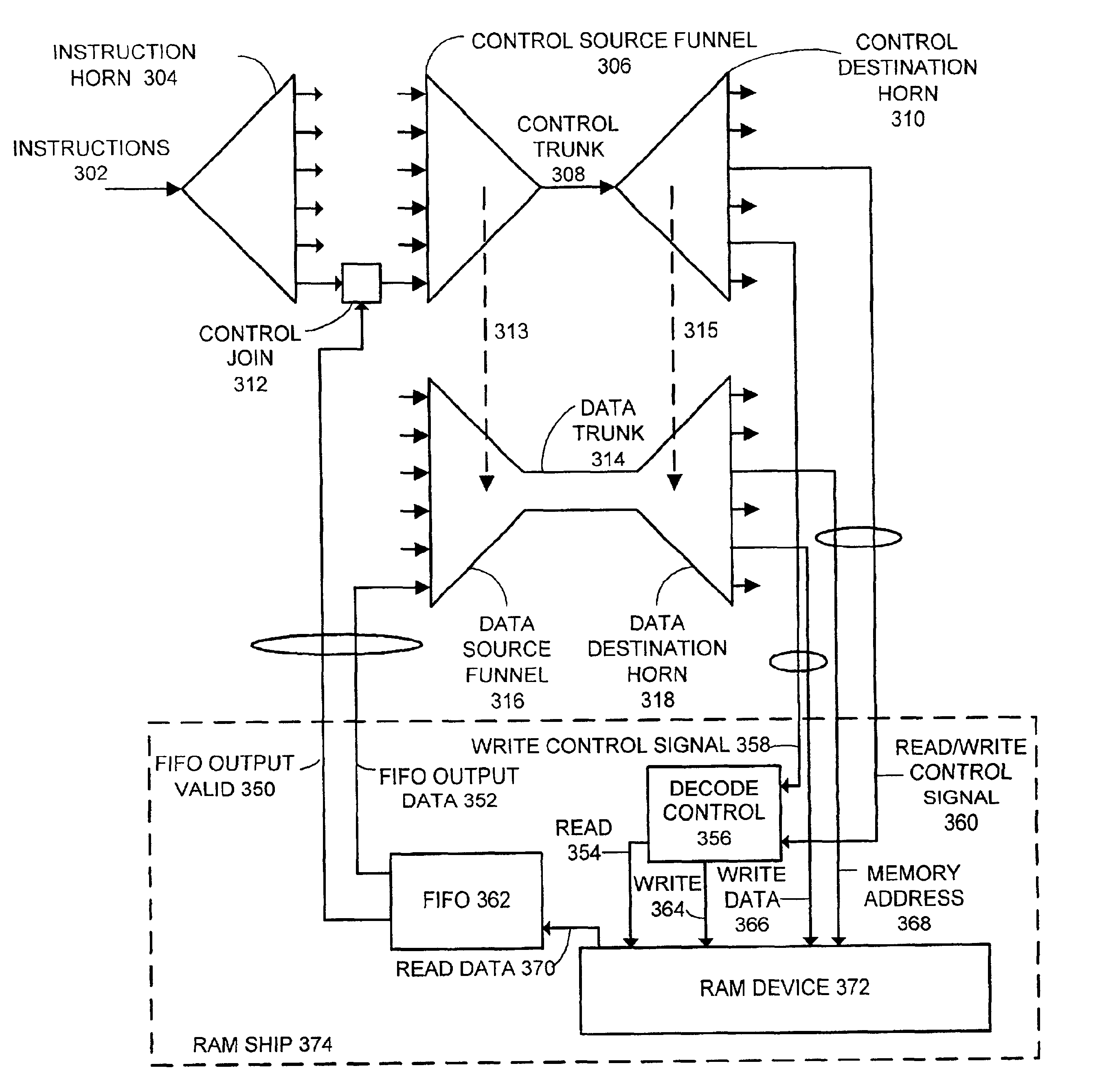
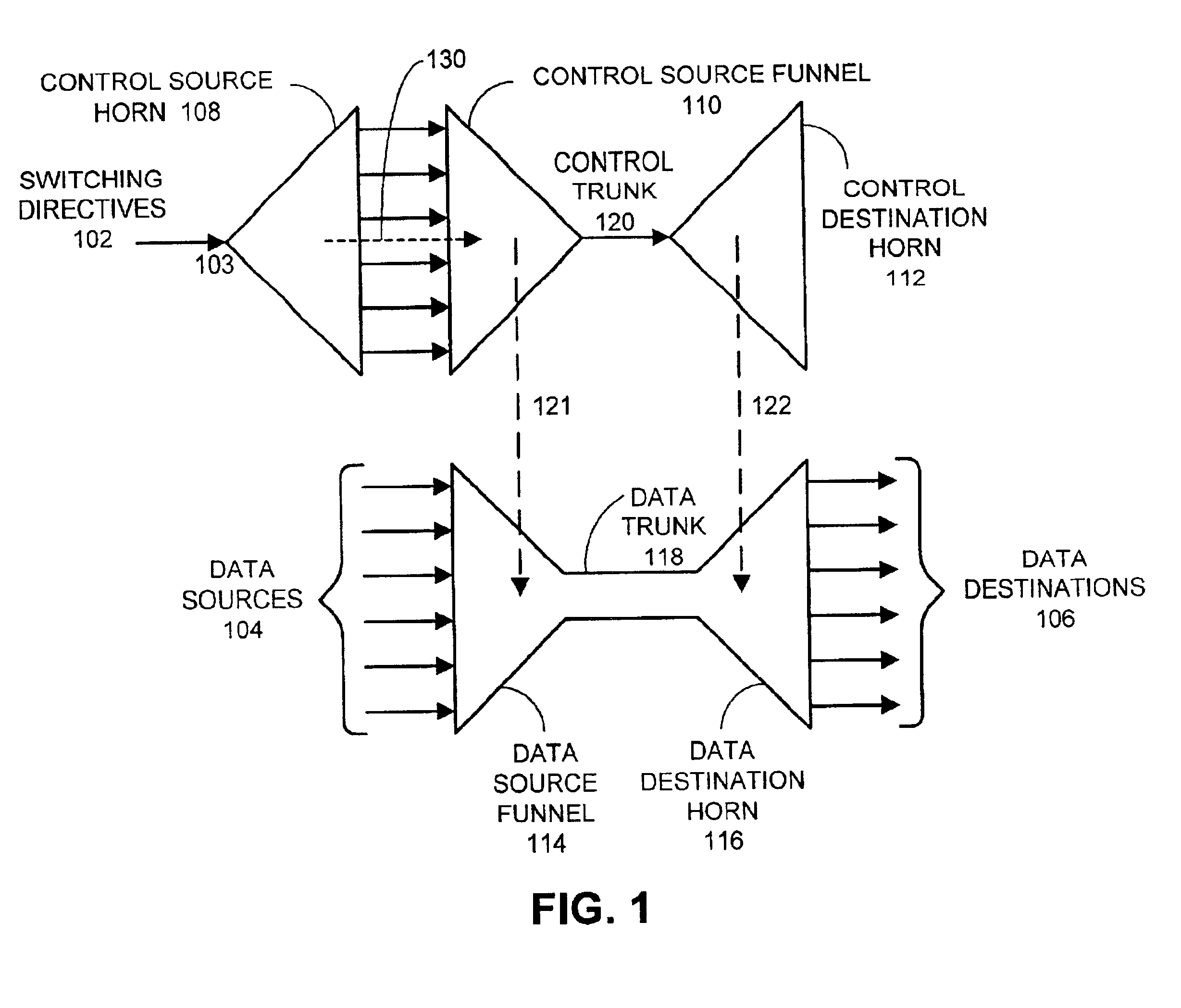
[0033]One embodiment of the present invention provides a system that facilitates implementing a memory mechanism within an asynchronous switch fabric. The system includes a memory device, which does not preserve first-in, first-out semantics such as a random access memory or a stack. The system also includes a data destination horn, for routing data from a trunk line to a plurality of destinations. The memory device is one destination of the plurality of destinations. The system further includes a data source funnel, for routing data from a plurality of sources into the trunk line. The memory device is a source of the plurality of sources.
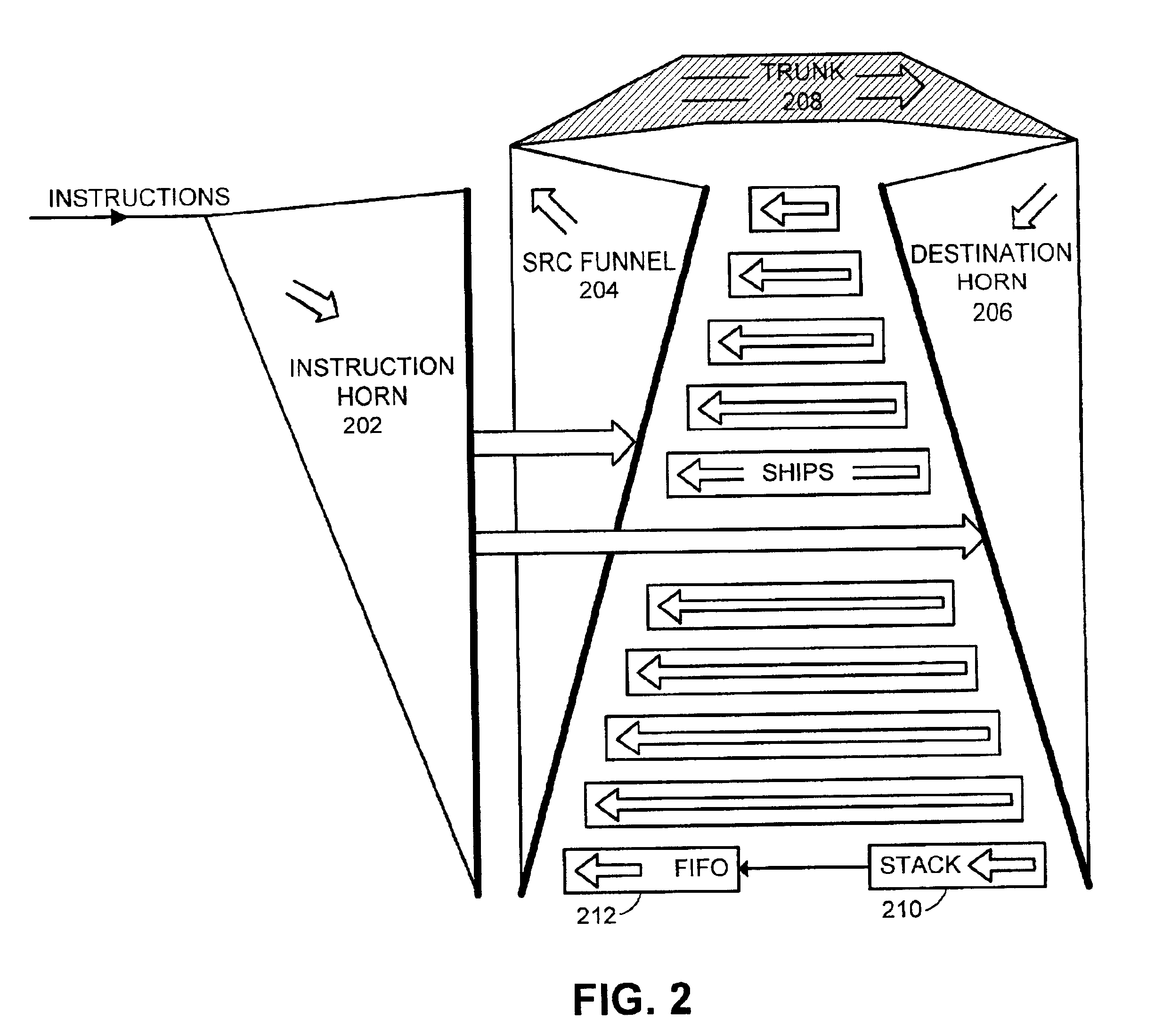
[0037]In one embodiment of the present invention, the system includes a first-in, first-out storage structure interposed between the memory device and the data source funnel. The first-in, first-out storage structure buffers the data from multiple reads permitting several outstanding reads from the memory to have completed before the data from the first read is delivered into the switch fabric. Use of a FIFO for this buffer ensures that data delivered from the memory device during the read operation will be available to the data source funnel in a same order as delivered from the memory device. Presence of the FIFO permits more concurrency with other operations. For example, a read request to the memory device can be placed early in the instruction stream and then a series of other instructions can be executed while the read takes place. The read data can then be selected in a later instruction when the data is needed. In this way, the later instruction does not need to wait for the read operation to be carried out—the data is already waiting in the FIFO. Note that it is also possible to interpose a FIFO between the memory device and the destination horn.
[0044]In one embodiment of the present invention, the apparatus converts the memory device with other than first-in, first-out semantics to into a dual-port device with first-in, first-out semantics so that read / write order hazards are avoided by assigning read and write control to a single port of the ship.

Problems solved by technology

There are a number of drawbacks to such a bus structure.
First, each destination must attach some transistors to the bus in order to sense the state of the bus, and because there are many destinations, these sensing transistors collectively represent a large electrical load.
Second, each source must attach driving transistors to the bus to drive data onto the bus, and even though all but one such drive transistor per bus wire is shut off when the bus changes state, the many inactive drive transistors connected to the bus also place considerable electrical load on the wires in the bus.
Third, the bus wires themselves tend to be physically long and thus intrinsically represent further electrical load.
The combined load on the bus wires from drivers, receivers and the wires themselves results in communication paths that are generally slow in comparison with other logical structures.
Furthermore, only a single piece of information can flow per bus cycle, which limits the achievable communication rate.
The disadvantage of the cross-bar switch lies in its large number of switching transistors.
Not only do these many switch points require chip area and consume power, but also they require control information.
The difficulty of controlling so many switches turns out to be a disadvantage in implementation.
However, like the cross-bar it suffers from the need for a great deal of control information.
Moreover, it is generally hard to find space for the large number of transmission lines required.
Generally, however, their control is very complex and their throughput is much less than that of an equivalent bus structure.
Thus, the design of such a structure is always a compromise between the desired speed and the space cost of extra wiring.
Thus, delivering information to all destinations always, will consume more power than would be required to deliver the same information only to its intended destination, leaving static the state of wires that do not participate in that particular communication.
In fact, the throughput of such a structure is limited mainly by its ability to turn the multiplexers on and off quickly enough.
Furthermore, consecutive communications from the same source to the same destination can overlap in time.
Naturally, a small time gap between communications is required; in the limit, however, there may be as many communications underway as there are levels in the tree-structures.
Naturally, the control of such a switching structure with internal storage presents its own set of challenges.
However, reading from and writing to elements that do not preserve FIFO semantics, such as a random access memory (RAM) device or a device with last-in, first-out (LIFO) semantics such as a stack, present a problem in this asynchronous architecture.
The problem arises because the read and write ports of these devices are connected to different locations in the switch fabric—the read port of the device is connected as a data source for the switch fabric, while the write port of the device is connected to a destination address of the switch fabric—and the switch fabric does not preserve instruction order at these different locations.
This can cause what are known as read-after-write hazards and write-after-read hazards.
Such non-deterministic behavior can be undesirable in many applications of the switch fabric.
The system includes a memory device, which does not preserve first-in, first-out semantics such as a random access memory or a stack.

Method used


Image

  • Apparatus and method for sequencing memory operations in an asynchronous switch fabric
  • Apparatus and method for sequencing memory operations in an asynchronous switch fabric
  • Apparatus and method for sequencing memory operations in an asynchronous switch fabric

Examples


Embodiment Construction

[0054]The following description is presented to enable any person skilled in the art to make and use the invention, and is provided in the context of a particular application and its requirements. Various modifications to the disclosed embodiments will be readily apparent to those skilled in the art, and the general principles defined herein may be applied to other embodiments and applications without departing from the spirit and scope of the present invention. Thus, the present invention is not intended to be limited to the embodiments shown, but is to be accorded the widest scope consistent with the principles and features disclosed herein.

Switching System

[0055]FIG. 1 illustrates a switching system for data in accordance with an embodiment of the present invention. A data path structure including a data source funnel 114, a data trunk 118, and a data destination horn 116 can carry information from any of the sources 104 to any of the destinations 106. Data source funnel 114 inclu...


PUM


Abstract

One embodiment of the present invention provides a system that facilitates implementing a memory mechanism within an asynchronous switch fabric. The system includes a memory device, which does not preserve first-in, first-out semantics such as a random access memory or a stack. The system also includes a data destination horn, for routing data from a trunk line to a plurality of destinations. The memory device is one destination of the plurality of destinations. The system further includes a data source funnel, for routing data from a plurality of sources into the trunk line. The memory device is a source of the plurality of sources.

Description

RELATED APPLICATIONS[0001]This application hereby claims priority under 35 U.S.C. §119 to a Provisional Patent Application entitled, “Apparatus and method for sequencing memory operations in an asynchronous switch fabric,” filed Mar. 13, 2001 by inventor Ian W. Jones (Application No. 60 / 275,585).[0002]The subject matter of this application is related to the subject matter in a non-provisional application by inventors Ivan E. Sutherland, William S. Coates and Ian W. Jones, entitled “Switch Fabric For Asynchronously Transferring Data Within A Circuit,” having Ser. No. 09 / 685,009, and filing date of Oct. 5, 2000.BACKGROUND[0003]1. Field of the Invention[0004]The present invention relates to the design of digital circuits. More specifically, the present invention relates to an apparatus and a method for sequencing memory operations to and from memory devices connected to an asynchronous switch fabric. Example memory devices are random access memories (RAMs) and last-in, first-out (LIFO)...

Claims


Application Information

Patent Timeline
Patent Type & Authority Patents(United States)
IPC IPC(8): G06F15/16G06F15/173H04L12/56
CPCG06F15/17393H04L49/103H04L49/3036H04L49/254H04L49/25
Inventor JONES, IAN W.
Owner ORACLE INT CORP
Learn More