
Direct conversion receiver apparatus

a receiver and receiver technology, applied in the field of direct conversion receivers, can solve the problems of b>1/b>passing unwanted signals of preselector filters, superheterodyne receivers using expensive and non-integrable rf, and components, etc., to achieve the effect of suppressing spurious responses

Inactive Publication Date: 2005-04-19
MEDIATEK INC
View PDF13 Cites 39 Cited by
  • Summary
  • Abstract
  • Description
  • Claims
  • Application Information

AI Technical Summary

Benefits of technology

[0034]A fourth aspect of the present invention is a frequency translation apparatus. The frequency translation apparatus includes a local oscillator to produce a local oscillation signal; a first modulation circuit to modulate the local oscillation signal; a first RF mixer to mix a received radio frequency signal with the modulated local oscillation signal; a demodulation circuit, receiving a first modulation signal and the mixed signal from the first RF mixer, to translate a first set of signals of

Problems solved by technology

While superheterodyne receivers are widely used, superheterodyne receivers use expensive and non-integrable RF and IF components such as bandpass filters.
As a result, superheterodyne receivers are not ideal for applications in small, low cost mobile communication systems such as cellular phones, pagers, cordless phones, and the like.
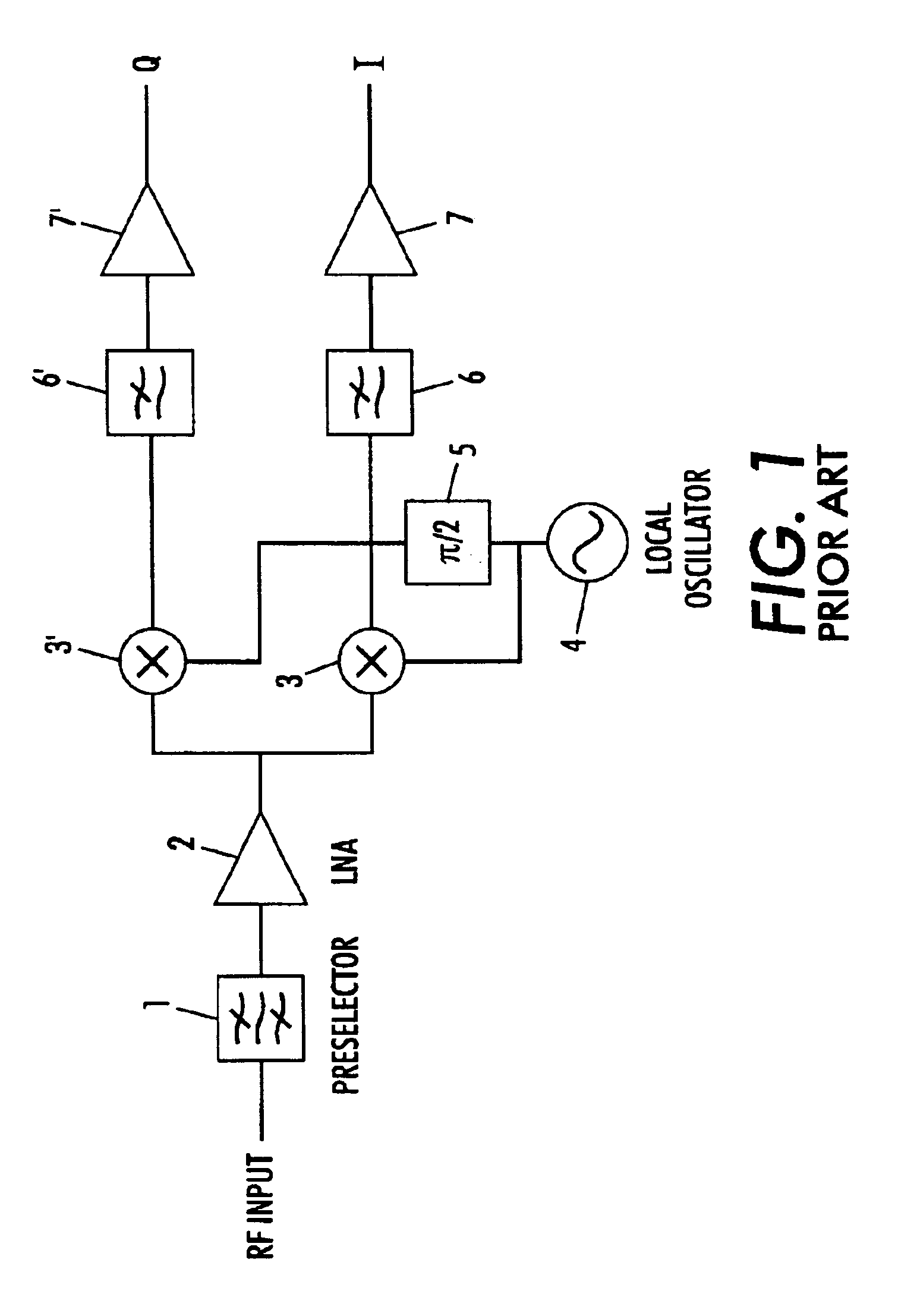
Furthermore, the preselector filter 1 may pass unwanted signals in addition to the desired signal.
Secondly, exception of the preselector filter, the direct conversion receiver employs only low pass filters rather than bandpass filters.
While there are advantages to direct conversion receivers over superheterodyne receivers, the traditional direct conversion receiver suffers from some disadvantages.
One problem with traditional direct conversion receivers is second-order distortion present in the mixer.
Second-order distortion is caused by the fact that a mixer is inherently a non-linear device.
Since the direct conversion receiver also shifts the desired signal to baseband, this second-order distortion produced by the mixer can significantly reduce the performance of the receiver.
While this method is effective to eliminate a DC offset, it is ineffective for distortion due to a non-constant envelope of an interferer.
Another problem with direct conversion receivers is spurious emissions.
The main source of spurious emissions in a direct conversion receiver is local oscillator leakage.
Other problems associated with direct conversion receivers are baseband offsets, low frequency noise, and drift.
Although the configuration of the “GPS Receiver RF Subsystem Design Overview” article reduces out-of-band interference, the disclosed receiver fails to substantially lower DC offsets while maintaining high spurious response rejection.
Although the direct conversion receiver of U.S. Pat. No. 6,192,225 reduces spurious emissions, the disclosed direct conversion receiver fails to substantially lower DC offsets or reduce sensitivity to amplitude modulation (AM) while maintaining high spurious response rejection.
Although the differential RF mixer circuit of U.S. Pat. No. 6,125,272 reduces the IM2 distortion element from the desired signal, the disclosed differential RF mixer circuit fails to substantially lower DC offsets or reduce sensitivity to amplitude modulation (AM) while maintaining high spurious response rejection.
However, a real circuit is nonlinear during the transitions, which are finite in duration, and thus the responses are not all non-zero, and result in spurious responses.
However, only slow changes in the DC can be removed by the feedback loop, not higher speed changes in the DC offset since these higher speed changes fall outside the bandwidth of the tracking loop.
However, radiation and dynamic re-reflection of the local oscillator signal at the antenna is still a significant problem.

Method used


Image

  • Direct conversion receiver apparatus
  • Direct conversion receiver apparatus
  • Direct conversion receiver apparatus

Examples


Embodiment Construction

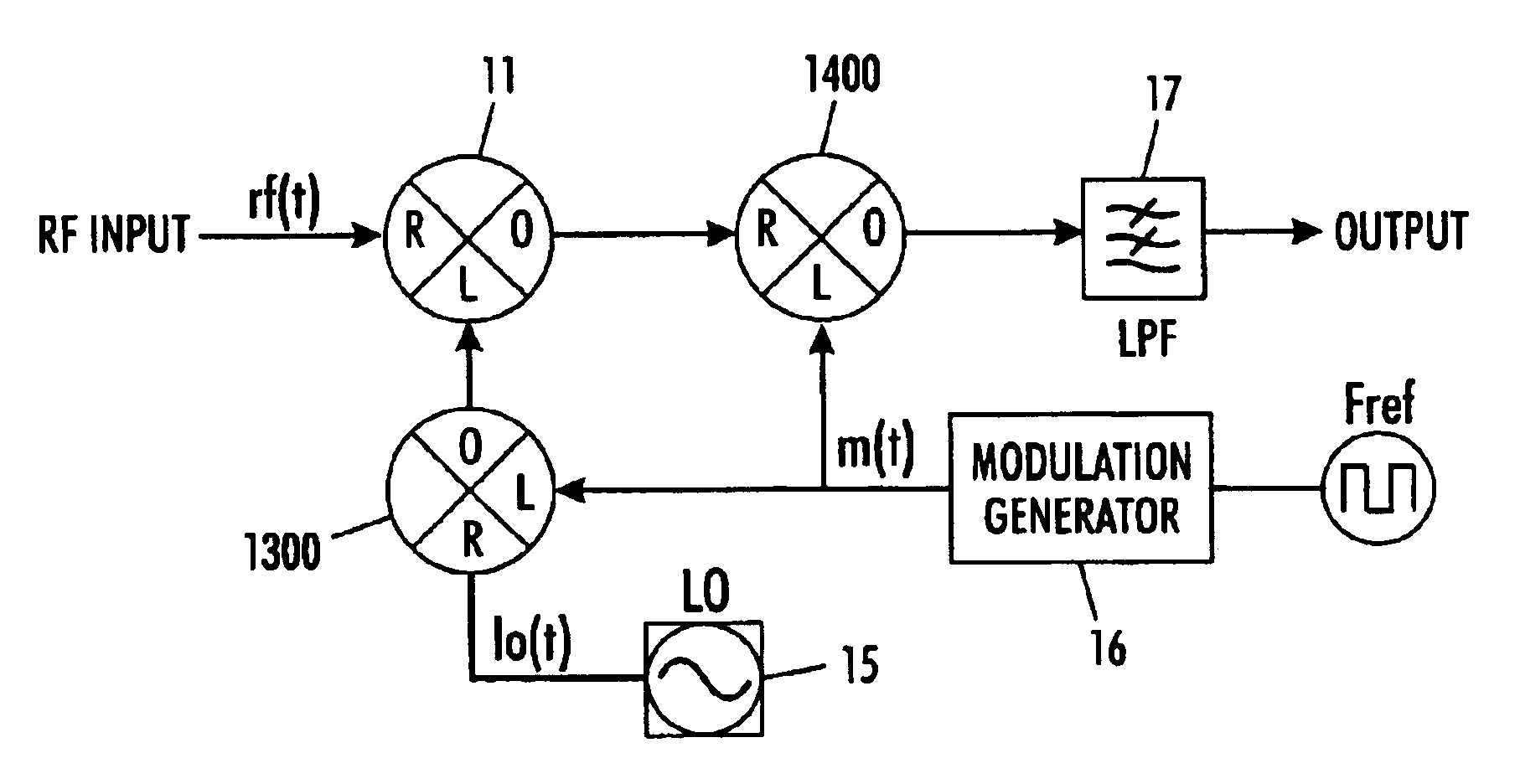
[0049]FIG. 3 illustrates a frequency translator wherein a local oscillator 15 produces a local oscillation signal, lo(t). A modulation circuit 130 modulates the local oscillation signal lo(t) with a signal m(t) from modulation generator 16 that generates signal m(t) in response to a received frequency. A RF mixer 11 mixes a received radio frequency signal rf(t) with the modulated local oscillation signal from modulation circuit 130. The mixed signal is fed to a demodulation circuit 140 that translates the desired signal of the mixed signal into band and translates undesired signal of the mixed signal out of band by demodulating the mixed signal with the signal m(t). The translated signal is then passed through a lowpass filter 17 to remove the undesired signals of the mixed signal.

[0050]In a further implementation, as illustrated in FIG. 4, a local oscillator 15 produces a local oscillation signal lo(t). A RF mixer circuit 1300 receives the local oscillation signal lo(t) at its radi...


PUM


Abstract

A direct conversion receiver apparatus includes a local oscillator to produce a first local oscillation signal and a second oscillation signal. A first modulation circuit modulates the first local oscillation signal, and a second modulation circuit modulates the second local oscillation signal. A RF mixer mixes a received radio frequency signal with the modulated first local oscillation signal, and another RF mixer mixes the received radio frequency signal with the modulated second local oscillation signal. Demodulating circuits translate desired signals of the mixed signal from the RF mixers into band and translate undesired signals of the mixed signal out of band. Filters remove the undesired signals from the demodulated signals.

Description

FIELD OF THE PRESENT INVENTION[0001]The present invention is directed to a direct conversion receiver employing a modulated local oscillator (LO) signal. More specifically, the present invention is directed to a direct conversion receiver that separates a received radio signal into its in-phase (I) and quadrature (Q) components while also reducing second-order intermodulation products due to non-linearities in the mixers while simultaneously maintaining high spurious response rejection.BACKGROUND OF THE PRESENT INVENTION[0002]A superheterodyne receiver is currently the most common type of receiver used in modern communications devices. Such receivers can be found in virtually any home, office, or automobile within a television set, telephone, or radio. A superheterodyne receiver mixes (or multiplies) an incoming radio-frequency (RF) signal (carrier at frequency f1) with a sinusoid signal (at a frequency f2) generated by a local oscillator. The resulting output signal comprises two f...

Claims


Application Information

Patent Timeline
IPC IPC(8): H04B1/30
CPCH04B1/30
Inventor BALBONI, EDMUND J.
Owner MEDIATEK INC
Learn More