Frequency converter

a frequency converter and converter technology, applied in the field of frequency converters, can solve the problems of reducing the consumption power of difficult to produce a compact transceiver, and difficult to control the generation of dc offsets by the frequency converter in the direct conversion receiver, so as to suppress spurious responses and intermodulation distortion products, the effect of removing dc offsets

Inactive Publication Date: 2005-06-30
ELECTRONICS & TELECOMM RES INST
View PDF4 Cites 9 Cited by
  • Summary
  • Abstract
  • Description
  • Claims
  • Application Information

AI Technical Summary

Benefits of technology

[0015] The present invention provides a frequency converter that can remove a DC offset and suppress spurious responses and intermodulation distortion products.

Problems solved by technology

Thus, it is difficult to produce a compact transceiver and reduce its consumption power.
Thus, it is difficult for the frequency converter in the direct conversion receiver to control the generation of DC offset caused by local oscillator signal self-mixing.
The DC offset saturates an automatic gain control (AGC) or a low pass filter, which is connected to the back end of the frequency converter, to cause a signal distortion and deteriorate the sensitivity of a receiver.
Furthermore, the frequency converter in the direct conversion receiver brings about second order intermodulation distortion.
However, the magnitude of the local oscillator signal LO applied to control turning on / off of the diodes 31 and 32 is as large as more than 0 dBm so that it may produce a lot of leakage components in the even harmonic mixer.
Therefore, the even harmonic mixer has high spurious response levels including even-order harmonics of the LO signal.

Method used


Image

  • Frequency converter
  • Frequency converter
  • Frequency converter

Examples


Embodiment Construction

[0027] The present invention will now be described more fully with reference to the accompanying drawings, in which exemplary embodiments of the invention are shown. The invention may, however, be embodied in many different forms and should not be construed as being limited to the embodiments set forth herein; rather, these embodiments are provided so that this disclosure will be thorough and complete, and will fully convey the concept of the invention to those skilled in the art. Throughout the drawings, like reference numerals refer to like elements.

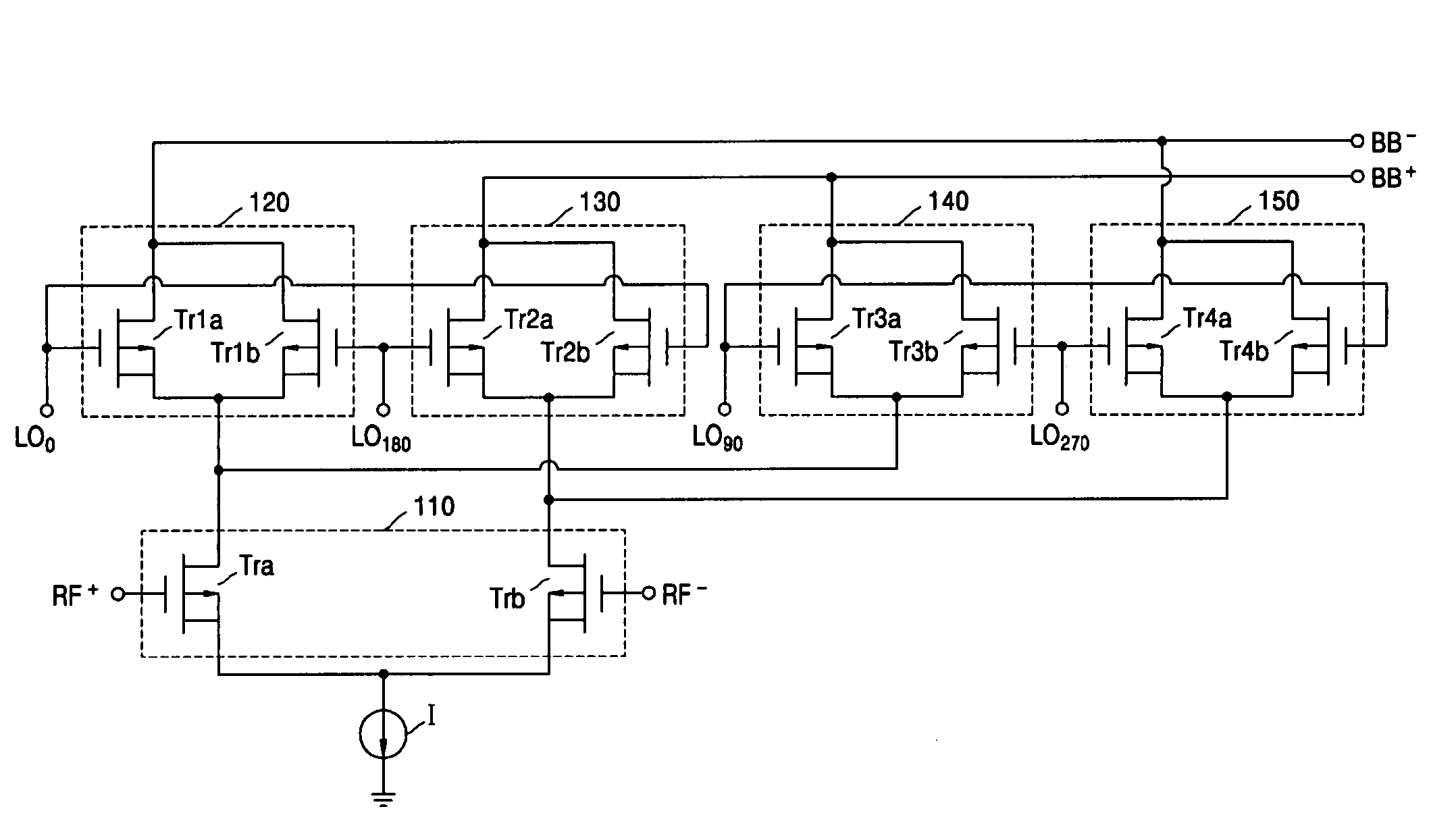
[0028]FIG. 4 is a circuit diagram of a frequency converter according to an embodiment of the present invention. Referring to FIG. 4, the frequency converter includes a reference signal input part 110, first, second, third and fourth frequency conversion parts 120, 130, 140 and 150.

[0029] The reference signal input part 110 includes a pair of first and second MOS transistors Tra and Trb connected in a differential amplifier form. Refe...


PUM


Abstract

Provided is a frequency converter that can remove a DC offset and suppress spurious response and intermodulation. The frequency converter receives a reference signal and a local oscillator signal and outputs a frequency component corresponding to the sum or difference of the reference signal and the even-order harmonics of local oscillator signal. The frequency converter includes a reference signal input part including a pair of MOS transistors connected in a differential amplifier form, which have gates to which positive and negative reference signals having a differential phase difference therebetween are respectively input, and first, second, third and fourth frequency conversion parts each of which is connected to the reference signal input part and includes a pair of MOS transistors. Local oscillator signals having a differential phase difference therebetween are input to the gates of the MOS transistors of the first and second frequency conversion parts. Local oscillator signals, which have phases orthogonal to phases of the local oscillator signals input to the first and second frequency conversion parts, are input to the gates of the MOS transistors of the third and fourth frequency conversion parts.

Description

BACKGROUND OF THE INVENTION [0001] This application claims the priority of Korean Patent Application No. 2003-96891, filed on Dec. 24, 2003, in the Korean Intellectual Property Office, the disclosure of which is incorporated herein in its entirety by reference. [0002] 1. Field of the Invention The present invention relates to a frequency converter and, more particularly, to a frequency converter that can remove a DC offset and a second order intermodulation distortion component. [0003] 2. Description of the Related Art A heterodyne architecture in a transmitting / receiving circuit on a wireless channel requires a plurality of separate components including a surface acoustic wave filter. Thus, it is difficult to produce a compact transceiver and reduce its consumption power. [0004] A direct conversion receiver directly converts a received reference signal to a baseband signal without converting it to an intermediate frequency so the receiver can be integrated into one chip. However, i...

Claims


Application Information

Patent Timeline
Patent Type & Authority Applications(United States)
IPC IPC(8): H03D7/14H04B1/26H04B1/40
CPCH03D7/1441H03D7/1408H03D7/1433H03D2200/0047H03D7/1475H03D7/1483H03D7/1458H04B1/26
Inventor SUNG, JIN BONGKANG, SUNG WEONHWANG, JUNG HWANHYOUNG, CHANG HEEKIM, YUN TAE
Owner ELECTRONICS & TELECOMM RES INST
Why Eureka
Try Eureka