NOx emission-control system using a virtual sensor

a technology of virtual sensors and nox, applied in the field of emission control systems, can solve the problems of increased burden on manufacturers, loss of nox reduction performance, and under-dosing of urea solutions, and achieve the effect of reducing the exhaust of the engin

Inactive Publication Date: 2005-04-19
CATERPILLAR INC
View PDF24 Cites 224 Cited by
  • Summary
  • Abstract
  • Description
  • Claims
  • Application Information

AI Technical Summary

Benefits of technology

[0009]In an embodiment of the present invention, a process for controlling emissions of an engine is provided. The process may include determining predicted NOx values based on a model reflecting a predetermined relationship between control parameters and NOx emissions, wherein the control parameters include ambient humidity, manifold pressure, manifold temperature, fuel rate, and engine speed associated with the engine. Further, the process may include adjusting the model based on a determination of whether the predicted NOx values meet a predetermined criteria associated with actual NOx values. The adjusted model may be stored in a memory associated with the engine whereby NOx emissions exhausted from the engine may be reduced based on virtual NOx emission values determined from the adjusted model.

Problems solved by technology

Growing government standards associated with combustion engine emissions have increased the burden on manufacturers to reduce the amount of nitrogen oxides (NOx) and particulates that may be exhausted from their developed engines.
However, the sometimes inverse relationship between fuel economy and reduced emissions tends to make the task of reducing NOx while meeting customer needs a daunting one.
Instituting these margins, however, may lead to under-dosing of the urea solution and loss of NOx reduction performance.
Although NOx reduction efficiency may be maximized using a closed-loop control process, the costs and maintenance associated with NOx sensing devices make implementing these processes in a SCR system unattractive to engine manufacturers.
Accordingly, the attenuated relationship between emission control functions and selected input and output parameters associated with the virtual sensors taught by Cheng et al. decreases the efficiency and accuracy of the ECM in controlling emissions.

Method used


Image

  • NOx emission-control system using a virtual sensor
  • NOx emission-control system using a virtual sensor
  • NOx emission-control system using a virtual sensor

Examples


Embodiment Construction

[0015]Reference will now be made in detail to the exemplary embodiments of the invention, examples of which are illustrated in the accompanying drawings. Wherever possible, the same reference numbers will be used throughout the drawings to refer to the same or like parts.

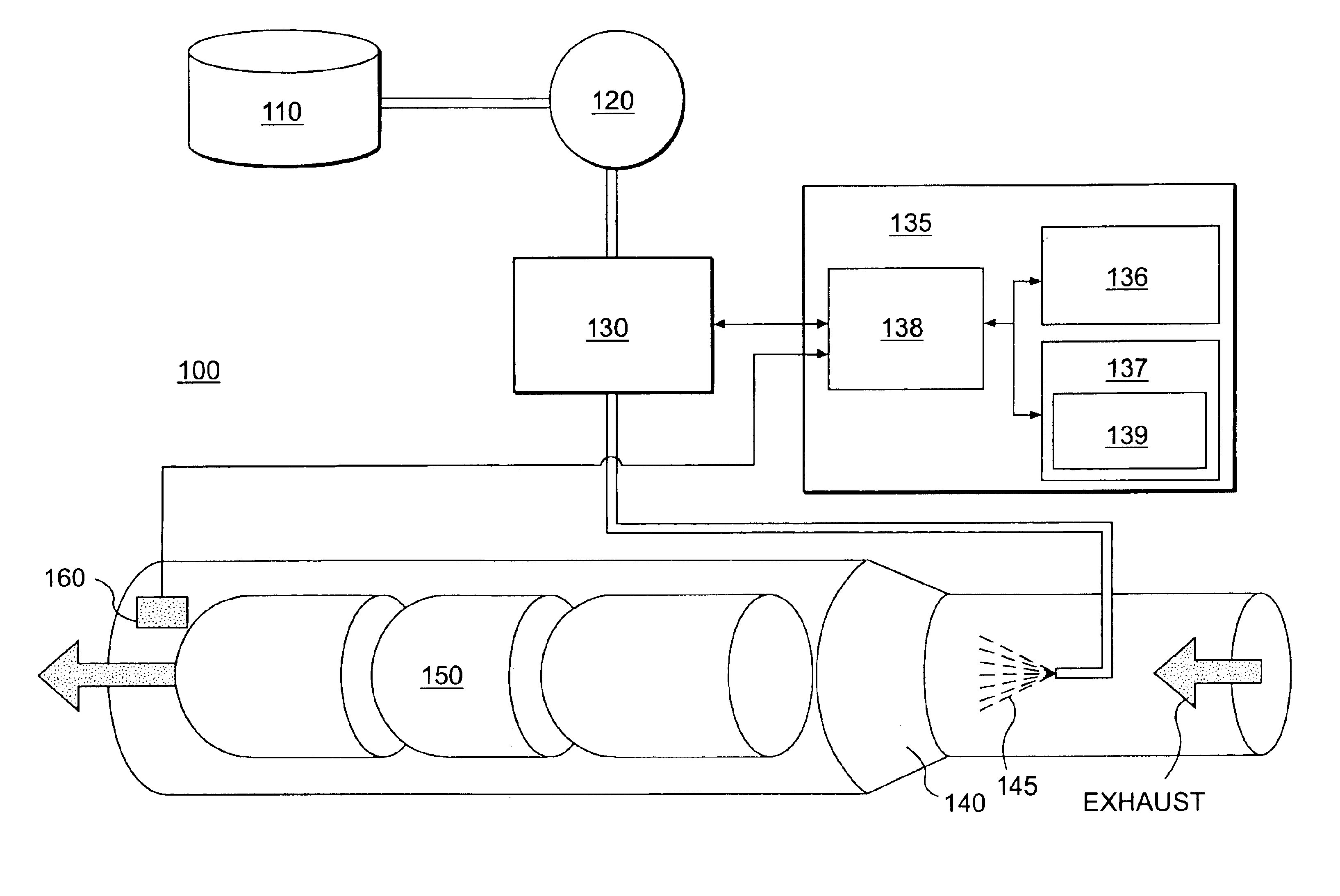
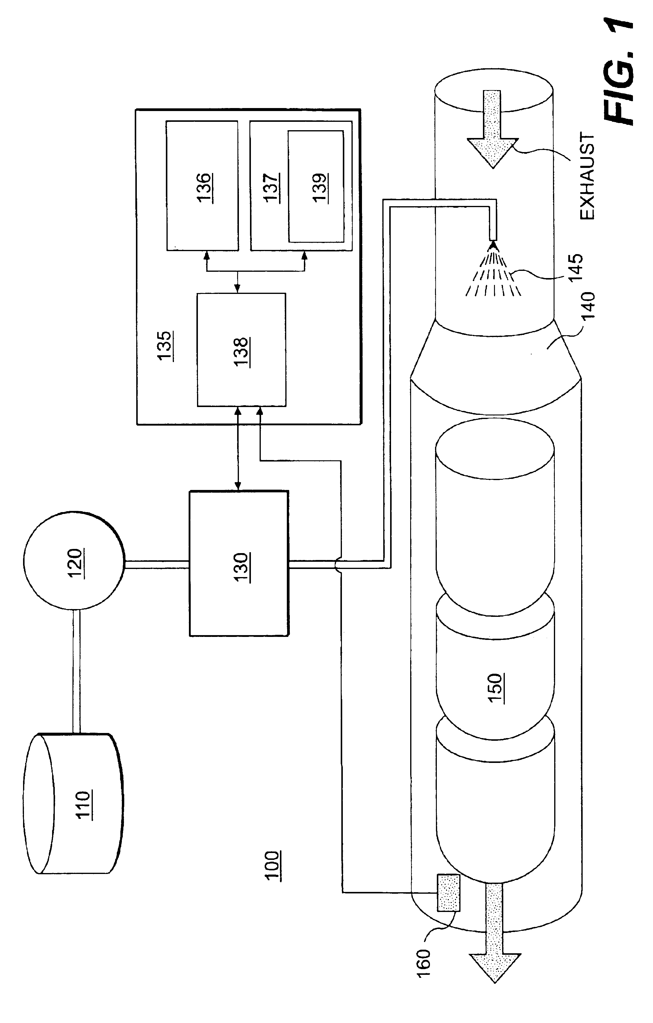
[0016]FIG. 1 illustrates an exemplary system 100 in which features and principles consistent with one embodiment of the present invention may be implemented. In one embodiment of the invention, system 100 may be associated with any type of machine engine, such as internal combustion type engines, that operate in various types of host systems. For example, system 100 may be affiliated with an engine associated with a marine vehicle, land vehicle, and / or an aircraft. Further, system 100 may be associated with an engine operating in a non-vehicle based system, such as machines operating within a manufacturing plant or generator sets. Moreover, while system 100 is shown for illustrative purposes in a urea-based SCR syst...


PUM


Abstract

A method and system may be provided to perform a process for controlling NOx emissions of an target engine. In one embodiment of the invention, the process may include determining predicted NOx values based on a model reflecting a predetermined relationship between control parameters and NOx emissions, wherein the control parameters include ambient humidity, manifold pressure, manifold temperature, fuel rate, and engine speed associated with the engine. Further, the process may include adjusting the model based on a determination of whether the predicted NOx values meet a predetermined criteria associated with actual NOx values. The adjusted model may be stored in a memory associated with the engine whereby NOx emissions exhausted from the engine may be reduced based on virtual NOx emission values determined from the adjusted model.

Description

TECHNICAL FIELD[0001]This invention relates generally to emission-control systems, and more particularly to methods and systems for controlling NOx emissions using virtual sensors.BACKGROUND[0002]Growing government standards associated with combustion engine emissions have increased the burden on manufacturers to reduce the amount of nitrogen oxides (NOx) and particulates that may be exhausted from their developed engines. Along with this burden is the manufacturer's commitment to their customers to produce fuel efficient engines. However, the sometimes inverse relationship between fuel economy and reduced emissions tends to make the task of reducing NOx while meeting customer needs a daunting one.[0003]One known type of NOx reduction technique is Selective Catalytic Reduction (SCR). This technique of reducing NOx in a combustion engine generally includes the use of selective reagents, such as ammonia, aqueous urea, and other types of ammonia containing compounds. In a conventional ...

Claims


Application Information

Patent Timeline
Patent Type & Authority Patents(United States)
IPC IPC(8): F01N3/20F02D41/14G05B13/04F01N7/00F01N9/00F02D41/02F01N7/02F02D45/00B01D53/34B01D53/56B01D53/74B01D53/94F01N3/08F01N13/02
CPCF01N3/208F01N13/0097F01N11/00F02D41/1405F02D41/1462G05B13/042F01N9/005F01N2560/026F01N2610/02F01N2900/14F01N2900/1402F02D41/0235F02D2041/1423F02D2041/1433Y02C20/10Y02T10/47Y02T10/24Y02T10/12Y02T10/40
Inventor LIANG, CHO Y.SRINIVASAN, SYAMAIAJACOBSON, EVAN E.
Owner CATERPILLAR INC
Why Eureka
Try Eureka