Muntin bars

a technology of insulating glass and muntin bars, which is applied in the field of system for fabricating muntin bars, can solve the problems of cost and efficiency, cost and efficiency, and the construction of conventional muntin bar constructions suffer from several drawbacks, and achieves the effects of improving quality, reducing labor intensity, and improving production efficiency

Inactive Publication Date: 2005-04-26
GED INTEGRATED SOLUTIONS
View PDF8 Cites 33 Cited by
  • Summary
  • Abstract
  • Description
  • Claims
  • Application Information

AI Technical Summary

Benefits of technology

[0015]The cross section of a completed muntin bar defines a perimeter that encloses an area having the general shape of a cross. The cross-shaped area defined by the perimeter of the formed muntin bar has two relatively narrow top and bottom legs and two relatively wide side legs. The length of the top and bottom legs is the same and the length of the two side legs is the same. The width of each leg tapers down along its length. A seam is formed at the end of one of the legs where two edges of the material used to form the tube meet. No welding of the seam is required after severing of the muntin bar. The severed bar can immediately be assembled into an attractive ready to install muntin bar grid.
[0016]Practice of the invention results in faster production of contoured muntin bars when compared to prior art production speeds. Using the apparatus and method of the disclosed invention, one person can make and assemble 1000 grid units during an eight hour shift compared to approximately 200 units when using fabrication techniques of the prior art. The cost per foot of muntin bar produced is also lower. The cost in making the contoured muntin bars using the invention is less than half the cost of making them with prior art apparatuses and the quality is better. More specifically, the invention produces higher quality, virtually seamless bars with precision cuts where the bar engages the window spacer frame and miters the muntin bars where they engage cross bars of the grid. The invention facilitates “just in time” manufacturing since the bars that make up a grid can be programmed into a controller and produced by the operator as other grids are being made. The controller optimizes the use of materials. The controller makes muntin bars for each grid in turn and then begins producing muntin bars for a subsequent grid based on a program of jobs programmed by the user. Excess payout of strip material is avoided and practice of the invention has reduced scrap material by at least 10 percent.

Problems solved by technology

Constructing muntin bar grids for insulating glass units has been a labor intensive process.
As a consequence, manufacturing such units, and thus windows formed by the units, has been costly and inefficient.
Conventional muntin bar constructions suffer from several drawbacks with respect to cost and efficiency.
This necessitates dedicated muntin bar stock storage space and increases costs associated with inventory.
Moreover, cutting the muntin bar stock frequently results in unusable scrap.
As a result, conventional construction of muntin bars and muntin bar grids requires the operator to perform a series of fabricating steps, thereby increasing the difficulty and cost associated with such construction.
The handling and notching procedures may also result in damage to the muntin bar finish and denting, or creasing.

Method used


Image

  • Muntin bars
  • Muntin bars
  • Muntin bars

Examples


Embodiment Construction

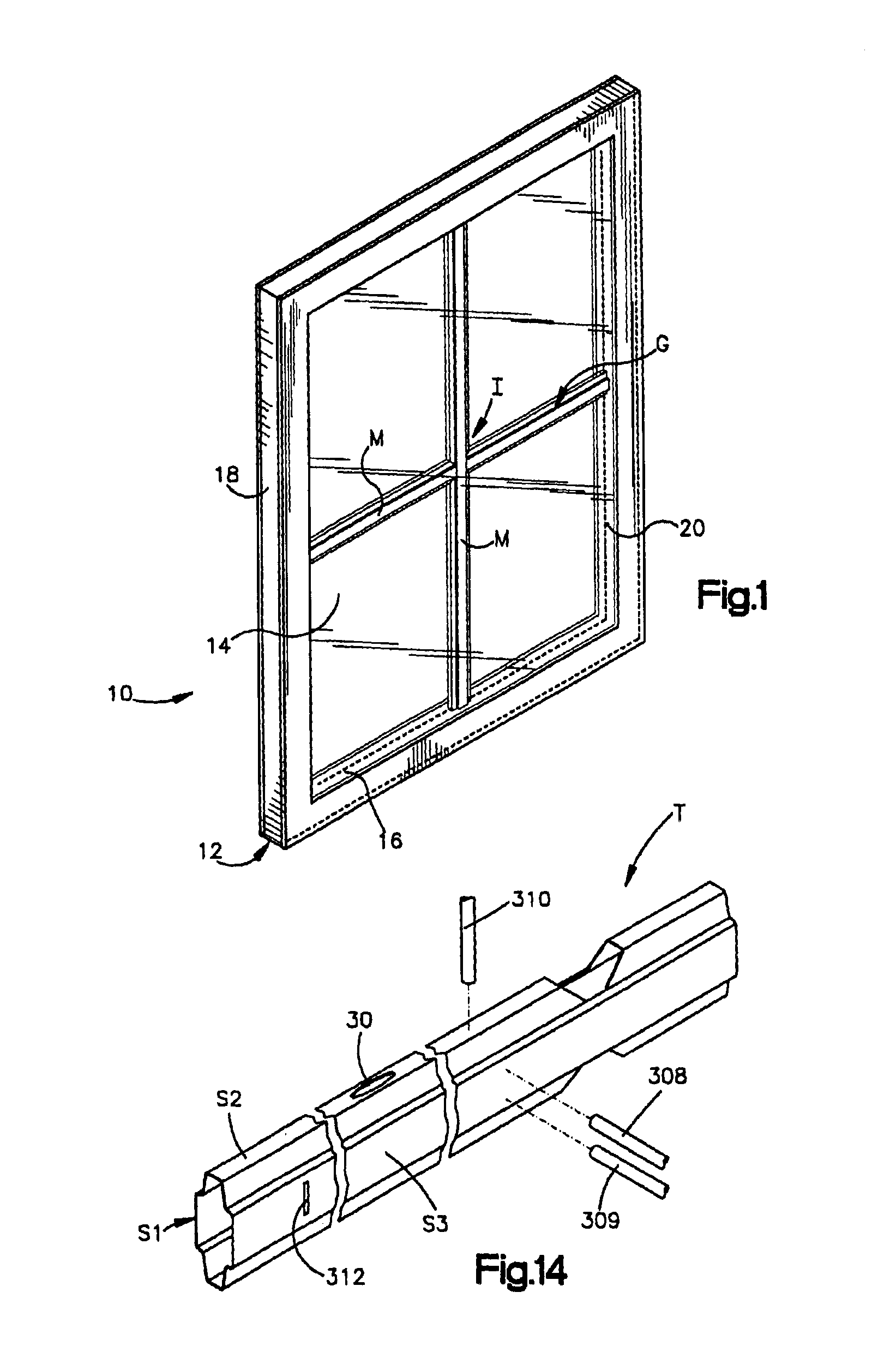
[0038]FIG. 1 shows an insulating glass unit indicated generally by the reference numeral 10 comprising a spacer assembly 12 sandwiched between glass sheets, or lights, 14. The spacer assembly 12 includes a frame assembly 16 hermetically joined to the glass lights by a sealant 18 to form a closed dead air space 20 between the lights. The unit 10 is illustrated in FIG. 1 in condition for assembly into a window or door frame (not shown).

[0039]A muntin bar grid G is disposed between the glass lights to provide the unit 10 with the appearance of a multi-pane window. Depending on the size of the glass sheet mounted in the spacer assembly the grid G can subdivide the glass sheet into different number of segments or panes. The light illustrated in FIG. 1 has been divided into four different panes, but many other configurations of muntin bar grids for dividing the lights into other numbers of panes is possible.

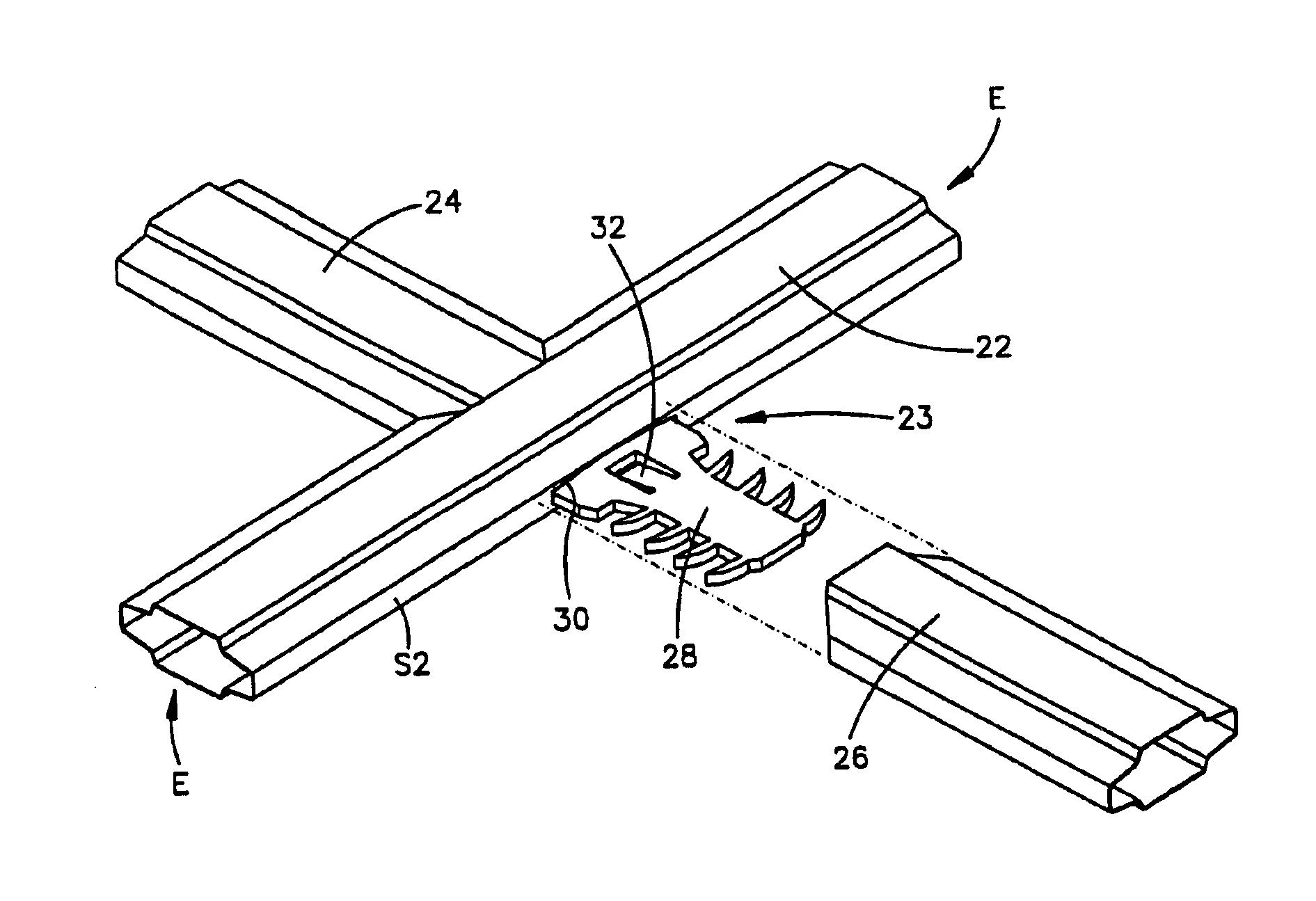
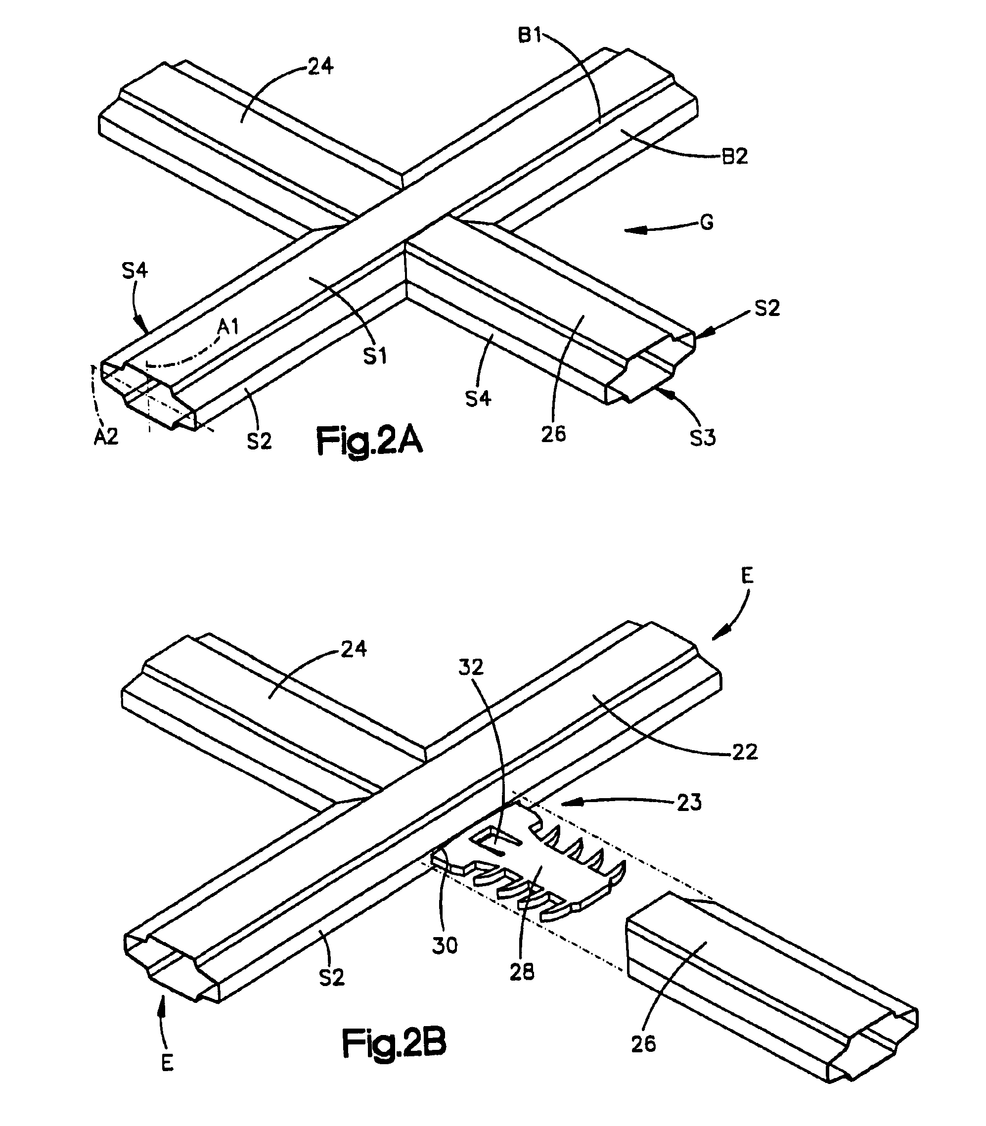
[0040]The muntin bars depicted in FIGS. 1, 2A, and 2B are contoured muntin bars. S...


PUM

PropertyMeasurementUnit
insulatingaaaaaaaaaa
notching lengthsaaaaaaaaaa
sizeaaaaaaaaaa

Abstract

Method and apparatus for making a contoured muntin bar. A supply of sheet material having a finished surface on at least one side in the form of a coiled ribbon is unwound and fed along a strip path of travel to a punch station. At the punch station a ribbon punching mechanism punches the ribbon at a precisely predetermined locations along the ribbon to form one of a plurality notch patterns that define a portion of a contoured muntin bar. Downstream along the travel path from the punch station the ribbon is fed through a forming station having a succession of forming rolls that define a succession of forming roll nips to bend the ribbon and form a generally closed cross-sectional tube. The rolls form a number of bending stages to produce a muntin bar tube having a contoured shape with raised sides to provide an attractive appearance to a muntin grid.

Description

CROSS REFERENCE TO RELATED APPLICATIONS[0001]This is a Divisional application of application Ser. No. 10 / 101,646 filed Jun. 20, 2002 now U.S. Pat. No. 6,651,304 which was a divisional application of application Ser. No. 09 / 525,349, filed on Mar. 15, 2000, now U.S. Pat. No. 6,438,819.FIELD OF THE INVENTION[0002]The present invention relates to the fabrication of insulating glass units for windows, and more particularly to a system for fabricating muntin bars used in the construction of insulating glass units.BACKGROUND ART[0003]Windows constructed from multiple glass panes utilized “muntins” or “muntin bars” to secure the edges of the individual glass panes within the window sash. In many windows, muntins formed distinctive grid patterns that are associated with architectural styles of buildings containing the windows.[0004]Modern windows formed by insulating glass units utilize single glass lights separated by an insulating dead air space. Where a particular architectural “look” is ...

Claims


Application Information

Patent Timeline
Patent Type & Authority Patents(United States)
IPC IPC(8): B21D5/08B21D5/06E06B3/66E06B3/673E06B3/667
CPCB21D5/086E06B3/67304E06B3/667E06B3/6604Y10T29/49995Y10T428/139
Inventor MCGLINCHY, TIMOTHY B.KHALFOUN, MOHAMED CHRIFGRISMER, JOHN LOUIS
Owner GED INTEGRATED SOLUTIONS
Why Eureka
Try Eureka