Light source device, illumination device liquid crystal device and electronic apparatus

a liquid crystal device and light source technology, applied in the direction of television systems, identification means, instruments, etc., can solve the problems of undesirable properties, no directivity in condensation of light emitted from a spherical lens used in the light source device, so as to improve the efficiency of incidence of light exiting, improve the effect of light emitted, and improve the light emitted ability of the light sour

Inactive Publication Date: 2005-04-26
BOE TECH GRP CO LTD
View PDF21 Cites 143 Cited by
  • Summary
  • Abstract
  • Description
  • Claims
  • Application Information

AI Technical Summary

Benefits of technology

[0032]Furthermore, in the illumination device as a component of each of the liquid crystal devices according to the first and second aspects, the lens can be provided on the light source device side, and the lens can also be provided on the light receiving plane of the light guide. When it is desired to improve the efficiency of incidence of the light exiting from the light source device on the light guide, lenses are preferably provided on both the light source device side and the light guide side. As a result, a bright display easy to see can be performed on the display plane of the liquid crystal device.
[0033]In order to achieve the fourth object, an electronic apparatus acco

Problems solved by technology

However, the aspherical lens used in the light source device disclosed in Japanese Unexamined Patent Application Publication No. 62-105486 is nondirectional, i.e., it has no directivity in condensation of the light emitted from the light emitting device.
Although the non-directivity for condensation of light is a preferable property according to circumstances, it is an undesirable property according to circumstances.
For

Method used


Image

  • Light source device, illumination device liquid crystal device and electronic apparatus
  • Light source device, illumination device liquid crystal device and electronic apparatus
  • Light source device, illumination device liquid crystal device and electronic apparatus

Examples


Embodiment Construction

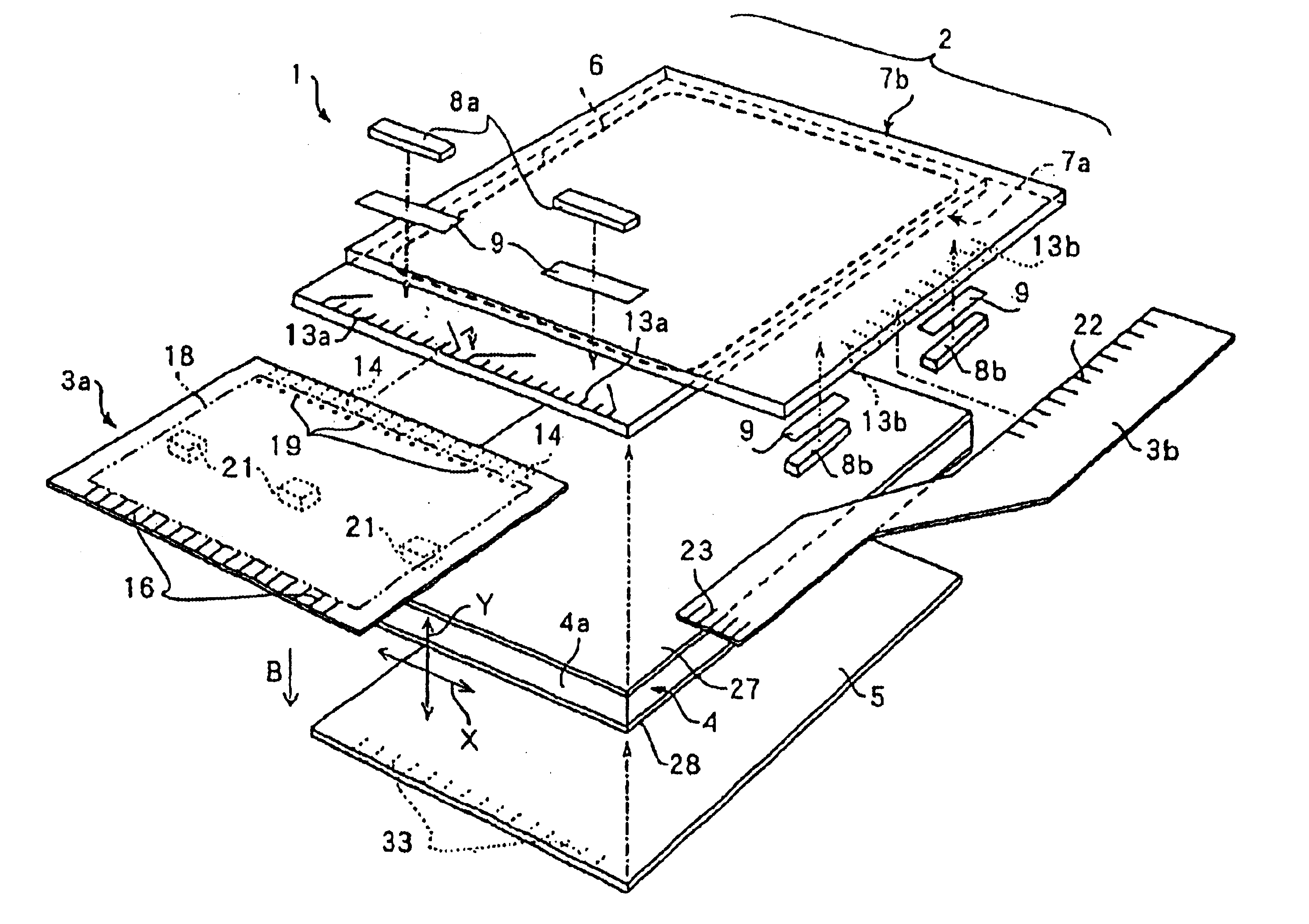
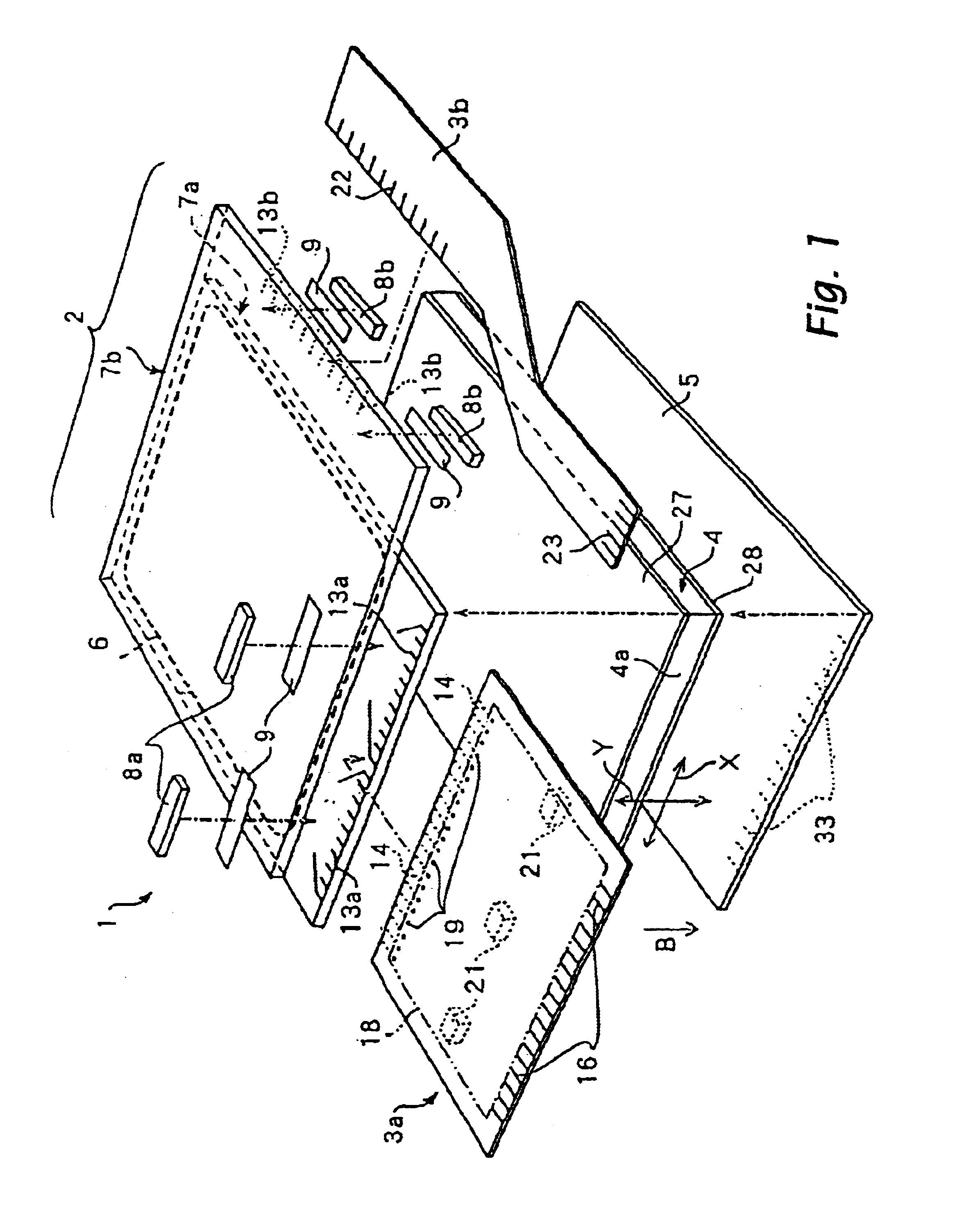
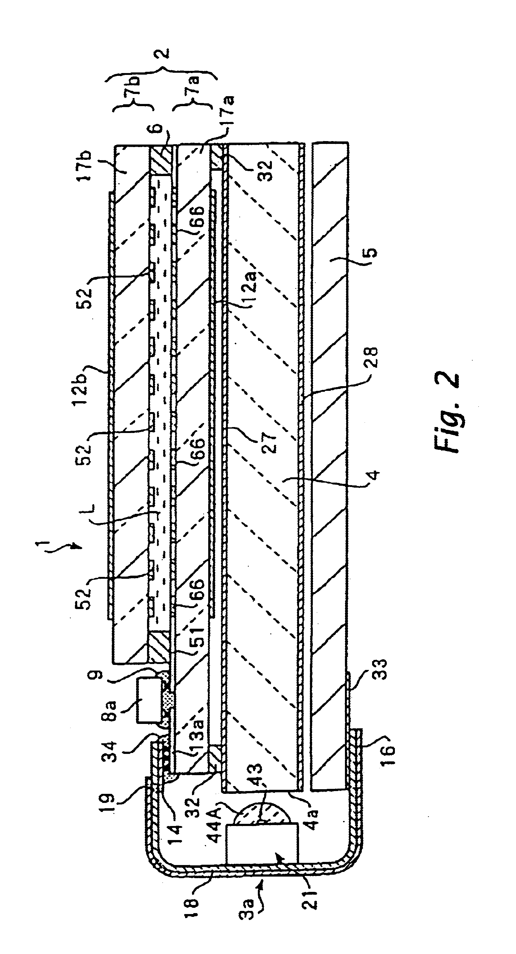
[0046]FIG. 7(a) shows a light source device according to an embodiment of the present invention. The light source device 41A shown in the drawing comprises a light emitting device 43 provided on the surface of a base 42, and a lens 44A provided on the light emitting plane of the light emitting device 43. The lens 44A is formed in a semicircular pillar shape, i.e., a so-called semicylindrical shape. The base 42 and the lens 44 may be formed separately and then boded together, or may be formed integrally.

[0047]The light emitting device 43 comprises, for example, a LED (Light Emitting Diode). When it is desired to obtain white light from the light source device 41A, for example, a blue LED is used as the light emitting device 43, and a resin containing a YAG fluorescent material is provided on the light receiving plane of the blue LED. As a result, a part of the blue light emitted from the blue LED is applied to the YAG fluorescent material to be converted to yellow light (i.e., mixtur...


PUM


Abstract

A light source device 41A, 41B or 41C comprising a lens 44A, 44B or 44C which receives light from a light emitting device 43 such as LED. The lens 44A is a lens having the property that the directivity of exiting light in the Y direction is higher than the directivity in the X direction perpendicular to the Y direction. Namely, the light emitted from the light emitting device 43 is condensed in a narrow angular range in the Y direction, and is scattered in a wide angular range in the X direction. When the light source device 41A is used as a light source of an illumination device of a liquid crystal device, the height direction of a light guide in which the dimension is small coincides with the Y direction, and the width direction of the light guide in which the dimension is large coincides with the X direction.

Description

BACKGROUND OF THE INVENTION[0001]1. Technical Field of the Invention[0002]The present invention relates to a light source device using a light emitting device such as LED (Light Emitting Diode) or the like, an illumination device using the light source device, a liquid crystal device using the illumination device, and an electronic apparatus using the liquid crystal device.[0003]2. Description of the Related Art[0004]Recently, liquid crystal devices have widely been used for electronic apparatuses such as a computer and a cell phone. The liquid crystal device generally comprises a liquid crystal sandwiched between a pair of substrates each comprising an electrode so that the orientation of the liquid crystal is controlled by applying a voltage between both electrodes to modulate light transmitted through the liquid crystal, to display an image.[0005]On the basis of the system for supplying light to the liquid crystal, various known liquid crystal devices are distinguished into a ref...

Claims


Application Information

Patent Timeline
IPC IPC(8): F21V8/00G02F1/1335G02F1/13F21Y101/02G02B6/00G02F1/13357G09F9/00H01L33/58H04N5/64H04N5/66
CPCG02F1/133615G02B6/003G02B6/0016G02B6/0051G02F1/1335
Inventor KAWAKAMI, HISANORIENDO, KOGO
Owner BOE TECH GRP CO LTD
Why Eureka
Try Eureka