Multicell cyclone and method for producing it

a multi-cell cyclone and cyclone technology, applied in the field of multi-cell cyclones, can solve the problems of clogging individual cyclone cells, negative separation effect, and inability to combine unlimited number of cyclone cells in a multi-cell, and achieve the effects of improving reliability of multi-cell cyclones, cost-effective production, and contributing to the economic efficiency of inventive multi-cell cyclones

Inactive Publication Date: 2005-04-26
MANN HUMMEL GMBH
View PDF12 Cites 34 Cited by
  • Summary
  • Abstract
  • Description
  • Claims
  • Application Information

AI Technical Summary

Benefits of technology

[0012]Another embodiment of the invention provides that the groups of cyclone cells are combined into individual modules. These modules have module housings, which in turn form small collection chambers for the separated substances. These collection chambers are provided with openings that discharge into the channel structures inside the cyclone housing. In this manner, the multicell cyclone is formed, as it were, by a plurality of very small multicell cyclones in the form of the modules. These modules advantageously comprise 4 to 10 cells, since suction for this number of cyclone cells by means of a common collection chamber is still completely unproblematic. The openings of the modules, however, end in the above-described channel structures, so that all the modules can be vacuumed out in the same way by suction through the particle discharge. This effectively counteracts clogging of the individual modules as described above.
[0013]In accordance with one preferred embodiment of the invention, the modules in turn form units that can be individually inserted into the housing for suction. In this manner, a modular system is realized. The modules can be cost-effectively produced and can be assembled into multicell cyclones in different housings with different numbers of cyclone cells. Thus, the variant with individual modules especially contributes to the economic efficiency of the inventive multicell cyclone.
[0014]According to another advantageous embodiment of the invention, the groups of cyclone cells, which can also be formed by the above-described modules, are uniformly arranged. This means, in particular, that the groups of cyclone cells are arranged symmetrically around a central axis. This symmetrical arrangement has the effect that ordered flow conditions are produced inside the housing. Consequently, the separation result by the particle discharge becomes more predictable and the reliability of the multicell cyclone is improved.
[0015]In a particularly advantageous embodiment of the invention, the channel structures comprise an annular channel, which encircles all the groups of cyclone cells. This annular channel makes it possible in a simple manner to withdraw the separated

Problems solved by technology

However, it is not readily possible to combine an unlimited number of cyclone cells in a multicell cyclone.
In operation, this may result in clogging in the individual cyclone cells.
This has a negative effect on the separation result of the multicell cyclone and the p

Method used


Image

  • Multicell cyclone and method for producing it
  • Multicell cyclone and method for producing it
  • Multicell cyclone and method for producing it

Examples


Embodiment Construction

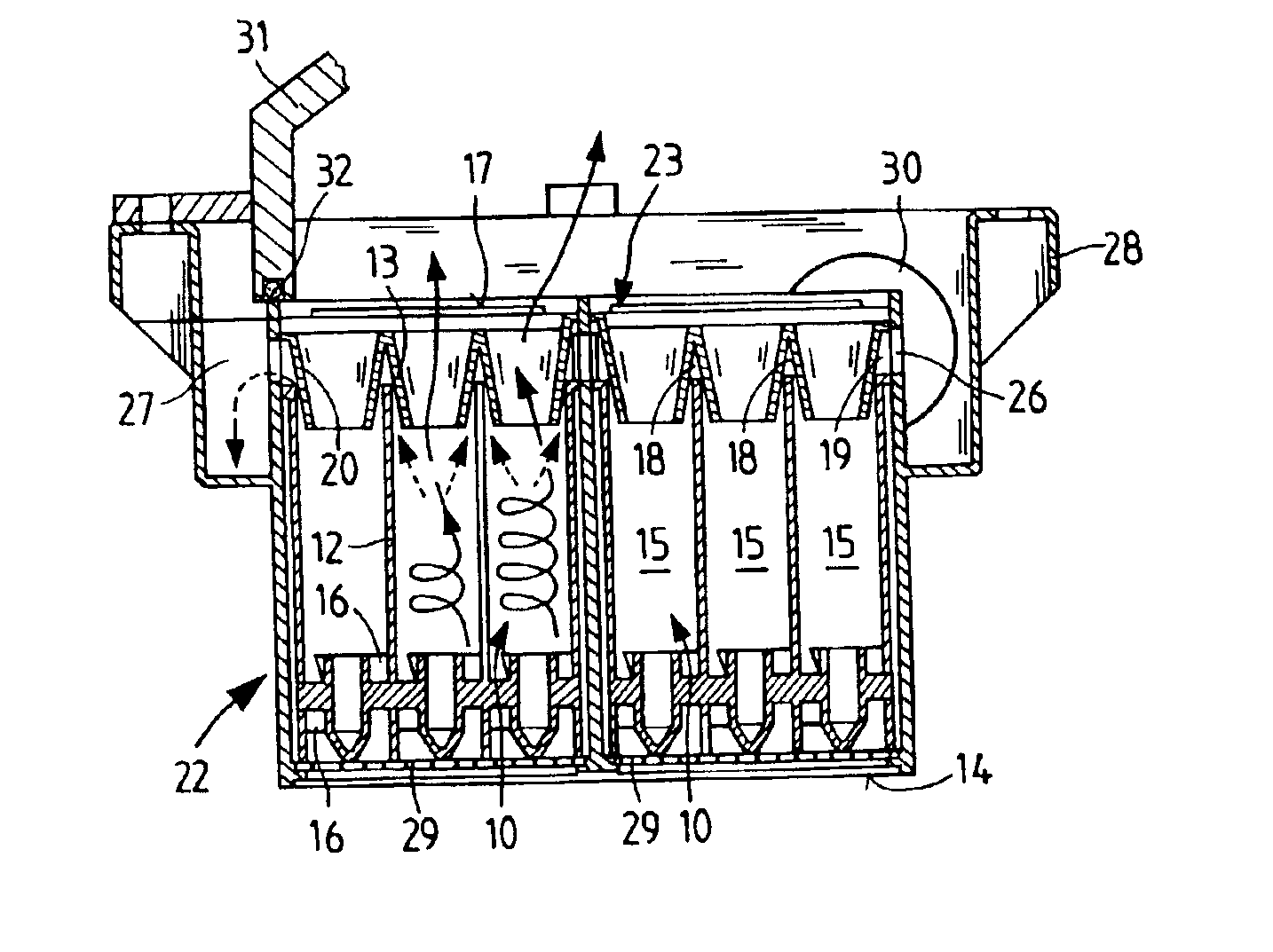
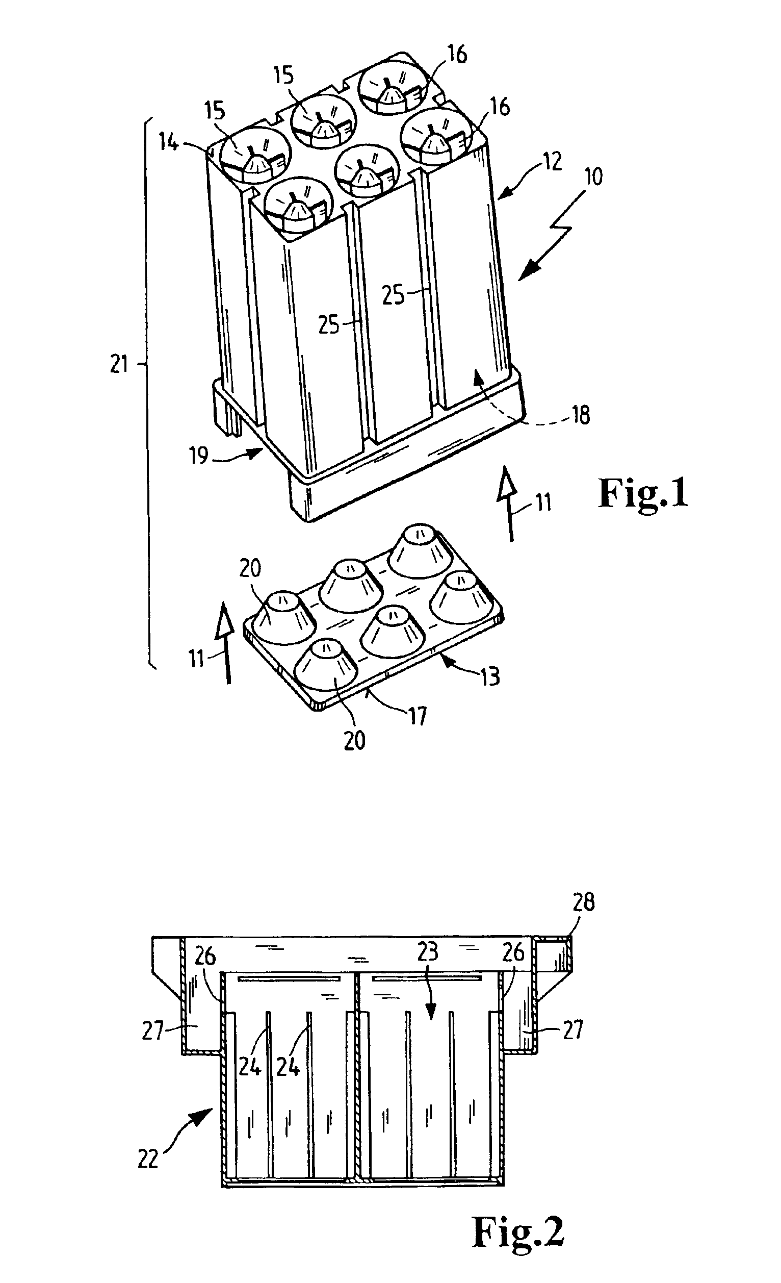
[0029]FIG. 1 shows a module 10 prior to assembly in accordance with the arrows 11. This module comprises a base body 12 and an attachment body 13. The base body forms an intake 14, which is formed by the opening of cyclone cells 15 on the untreated side. In these openings, guide vanes 16 may be seen, which are integrally formed with base body 12 without undercuts. Thus, the part shown can be produced by injection molding using two mold halves. These mold halves can be joined in the direction of arrows 11 and separated again after the injection molding process. The same also applies to the attachment body 13.

[0030]Attachment body 13 forms an outlet side 17, which is simultaneously configured as a cover to seal off a collection chamber 18 (not visible in FIG. 1), which is formed by the base body. In the parting line that is thereby created, an opening 19 is formed for discharging the separated substances deposited in collection chamber 18. From cyclone cells 15 the separated substance...


PUM

PropertyMeasurementUnit
Fractionaaaaaaaaaa
Electrical resistanceaaaaaaaaaa
Vacuumaaaaaaaaaa

Abstract

A multicell cyclone with a plurality of cyclone cells and a method for the production thereof, in which the cyclone cells of the multicell cyclone are combined into groups from which deposited particles are cleaned out by vacuum suction through channel structures. This permits better control of the discharge of separated particles. Vacuum suction of the separated particles can be effected, for instance, via openings (19) which are jointly provided for the group (21) of cyclone cells. The group of cyclone cells can furthermore be produced as a module, which can, for instance, be assembled from two parts (12, 13) in which like structural elements of a group of cyclones are combined into one respective part. This makes it possible to optimize the separation result with little structural complexity and at low production cost.

Description

BACKGROUND OF THE INVENTION[0001]The invention relates to a multicell cyclone comprising a plurality of cyclone cells connected in parallel. The invention further relates to a method for producing a group of such cyclone cells.[0002]Multicell cyclones of this type are known, for instance, from German Utility Model DE 298 19 335 U1. According to this document, the aforementioned multicell cyclones are used, for example, for the preliminary separation of particles in air filters. FIG. 1 of the aforementioned document shows a modular construction of the multicell cyclone in which the cyclone cells 20 are integrated between perforated plates 19. This creates a collection chamber between these perforated plates for the separated particles, which can be emptied through a particle discharge 26. The cyclone cells 20 are standard components and can therefore be produced cost-effectively due to the large production quantities. Combining the cyclone cells thus permits cost-effective implementa...

Claims


Application Information

Patent Timeline
IPC IPC(8): B01D45/12B04C3/04B04C3/00F02M35/022B04C5/28
CPCB04C3/04B01D45/12
Inventor KOPEC, EDVARDGREIF, VOLKERDWORATZEK, KLEMENSHAEHN, JENSHARTMANN, MARION
Owner MANN HUMMEL GMBH
Why Eureka
Try Eureka