Beam or wave front

a beam or wave front technology, applied in the field of improved beams, can solve the problems of inability to meet the requirements of manufacturing operations or processes, and inability to adjust the aperture,

Inactive Publication Date: 2005-04-26
HITACHI SEIKO LTD
View PDF12 Cites 7 Cited by
  • Summary
  • Abstract
  • Description
  • Claims
  • Application Information

AI Technical Summary

Benefits of technology

[0007]Another object of the present invention is to provide the beam with a profile which minimized the edge diffraction effect to result in the drilling or formation of a more uniform blind via, hole, aperture or some other desired formation in a surface to be processed.
[0008]A further object of the present invention is to accentuate the intensity of the beam or wave front about its perimeter, especially when drilling through metal surfaces, to facilitate a precise and uniform blind via, hole, aperture or some other desired formation in a surface to be processed while minimizing the amount of annealing, or some other undesired side effect, which may occur as a result of such drilling.
[0009]A further object of the present invention is to provide a more uniform plasma, as the laser beam strikes the surface of the object to be processed and to provide a more average extenuation of the plasma resisting the supply laser beam and this facilitates a more uniformly drilled or formed aperture or feature formed in the surface to be processed.
[0010]Yet another object of the present invention is to vary the intensity of the beam or wave front, from a center longitudinal axis of the beam or wave front radially outward toward the perimeter of the beam or wave front, to form a plurality of annular peaks and annular valleys which facilitate a more uniform formation of a blind via, hole, aperture or some other desired formation in a surface to be processed.
[0012]The present invention also relates to an improved beam for use in ablating a surface of an object to be processed, the improved beam front having a profile with a plurality of undulations, the plurality of undulations defining a plurality of annular peaks and annular valleys, and an intensity of the annular peaks being about 10 percent greater than an intensity of the annular valleys whereby the undulations of the improved beam facilitating formation of the uniform feature in the surface to be processed.
[0013]The present invention also relates to a method of utilizing an improved beam to form the desired feature in a surface to be processed, the method comprising the steps of: emitting a beam from a laser; shaping the emitted beam to have a profile with a plurality of undulations, the plurality of undulations defining a plurality of annular peaks and annular valleys, and an intensity of the annular peaks being about 10 percent greater than an intensity of the annular valleys; and contacting a surface to be processed with the improved beam so that the undulations of the improved beam facilitating formation of a uniform feature in a surface to be processed.

Problems solved by technology

The problem with this type of blind via or aperture is that a depth of the blind via or aperture tends to be deeper around the perimeter of the via than it is in the center.
This non uniformity results in a blind via or aperture which may be unacceptable for some manufacturing operations or processes.
The inventor believes that one of the problems associated with flat top or pseudo flat top wave fronts or beams is that edge diffraction occurs as the wave front or beam strikes or contacts the surface to be processed.
This edge diffraction has a tendency to increase the drilling depth of the blind via or aperture around the perimeter thereof and this results in a blind via or aperture which has an undesirable contour or profile.
However, one major problem with the laser beam 2, when drilling a blind hole in a desired object, for example, is the formation of an uneven base surface 6 at the bottom of the blind via 8.
This defect may increase manufacturing time, result in an improper fit of a desired component, or even possible rejection or discarding the object 14.
Therefore, the flat top wave front 4 is generally unacceptable for many manufacturing applications, especially when close tolerances are required.

Method used


Image

  • Beam or wave front
  • Beam or wave front
  • Beam or wave front

Examples


first embodiment

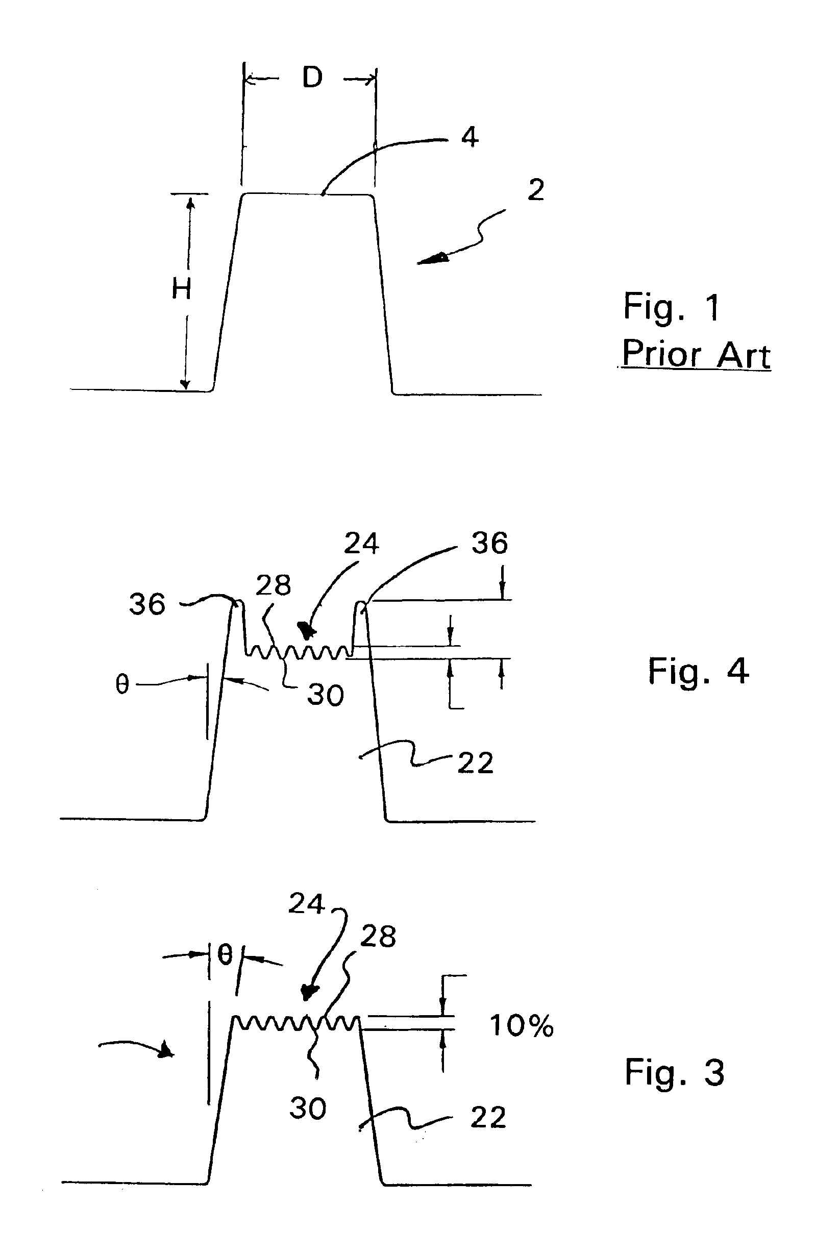
[0035]an improved laser beam 22, according to the present invention, is shown in FIG. 3. The inventor has determined that by altering the shape or profile of the wave front 24 of the laser beam 22 so that the wave front 24 has a plurality of undulations comprising a plurality of alternating annular peaks 28 and annular valleys 30 which extend radially from a center, or central longitudinal axis, of the beam 22. The improved laser beam 22, of the present invention, when contacting or striking a surface to be processed 32, facilitates a more uniform blind via, hole, aperture or other formation 34 in the surface of the object to be processed 32. If the blind via, hole, aperture or some other formation 34 in the surface of the object to be processed 32 can be adequately formed by a single or minimal amount of firings of the laser, this reduces the manufacturing time in order to obtain an acceptable blind via, hole, aperture or some other formation 34 in the surface of the object to be p...

second embodiment

[0036]FIG. 4 depicts the improved laser beam 22 according to the present invention. This embodiment is similar to the embodiment in FIG. 3 with the addition of an enlarged annular perimeter peak 36 circumscribing the entire perimeter of the wave front 24. The enlarged annular perimeter peak 36 is approximately 10-30 percent or so greater than the intensity of the annular valleys 30. This embodiment is particularly advantageous when drilling into an object 32 which comprise multiple layers of different materials, as can be generally seen in FIGS. 9A-9C. A further description concerning the same will follow below.

third embodiment

[0037]the improved laser beam 22, according to the present invention, is shown in FIG. 5. This embodiment is similar to the embodiment of FIG. 4 with the addition of an enlarged central peak 38. Enlarged central peak 38 further assists with an initial first cut into an object 32 prior to the remainder of the wave front 24 contacting the object to be processed 32. The enlarged annular perimeter peak 36 and the enlarged control peaks 38 both have an intensity which is approximately between 10 and 30 percent or so greater than the intensity of the annular valleys 30, and more preferably about 15 percent or so greater than the intensity than the annular valleys 30.


PUM

PropertyMeasurementUnit
perimeteraaaaaaaaaa
diameteraaaaaaaaaa
annular perimeteraaaaaaaaaa

Abstract

An improved beam for use in ablating a surface to be processed. The improved beam front has a profile with a plurality of undulation and the plurality of undulations define a plurality of annular peaks and annular valleys. An intensity of each annular peak is about 10 percent greater than an intensity of each annular valley whereby the undulation of the improved beam facilitates formation of a substantially uniform feature in the surface to be processed. A method of utilizing an improved beam to form the desired feature in a surface to be processed is also disclosed. To reduce energy losses, a fourier transform is performed on the supplied laser beam. Before striking the surface, this beam passes through a focusing lens which performs a reverse fourier transform and retransforms the wave front substantially back to its originally wave form and intensity.

Description

CROSS REFERENCES TO RELATED APPLICATIONS[0001]The present Application is related to and claims benefit of U.S. Provisional Patent Application Ser. No. 60 / 365,405 filed Mar. 18, 2002 by Todd E. Lizotte for an Improved Beam or Wave Front.FIELD OF THE INVENTION[0002]The present invention relates to an improved beam or wave front to facilitate a more uniform and concentric drilling or ablation in a surface of a substrate or object to be processed.BACKGROUND OF THE INVENTION[0003]In the prior art, there have been attempts to achieve a substantially flat top or pseudo flat top wave front or beam for use in a drilling or otherwise forming a blind via, hole, an aperture or other desired formation in a surface to be processed. One such pseudo flat top wave front or beam is generally shown in FIG. 1 of the drawings and this type of beam generally, when striking a surface to be processed, forms a blind via or aperture therein which has a shape generally depicted in FIG. 2 of the drawings. The ...

Claims


Application Information

Patent Timeline
Patent Type & Authority Patents(United States)
IPC IPC(8): B23K26/073B23K26/06G02B27/09
CPCB23K26/0656B23K26/0734G02B27/0955G02B27/0927G02B27/0944G02B27/09B23K26/066B33Y30/00
Inventor LIZOTTE, TODD E.
Owner HITACHI SEIKO LTD
Why Eureka
Try Eureka