Method and apparatus for determining electrical contact wear

Inactive Publication Date: 2005-04-26
NICHOLS APPLIED TECH
View PDF10 Cites 18 Cited by
  • Summary
  • Abstract
  • Description
  • Claims
  • Application Information

AI Technical Summary

Benefits of technology

[0009]The invention relates to an improved sacrificial electrical contact or interrupter assembly component. At least a portion of the electrical contact or interrupter assembly componen

Problems solved by technology

In high voltage equipment, the contacts of electrical switches operating under load generally erode over time during operation.
The erosion of electrical contacts most commonly results from the arcing that occurs whenever a switch breaks, or interrupts, a circuit.
The current flowing across the gap generates extreme heat, resulting in temperatures high enough to burn away some of the contact material.
Erosion of the contacts can cause failures or deteriorated switch operation and otherwise generally reduce or limit the useful lives of the switches themselves.
Switches may fail when their contacts have eroded to such a degree that they cannot effectively complete a circuit, or when the erosion has changed the physical shape of the contact such that the mechanical operation of the switch is interrupted.
Once a contact has eroded to the point at which further use risks injury to personnel or machinery, known as the “critical point,” a contact's useful life is over.
Replacing worn contacts at or before the critical point is important because contacts used past that point continue to erode and may cause the switch to fail.
A switch failure can have a negative or catastrophic effect on equipment and presents a danger to personnel.
On the other hand, replacing contacts be

Method used


Image

  • Method and apparatus for determining electrical contact wear
  • Method and apparatus for determining electrical contact wear
  • Method and apparatus for determining electrical contact wear

Examples


Embodiment Construction

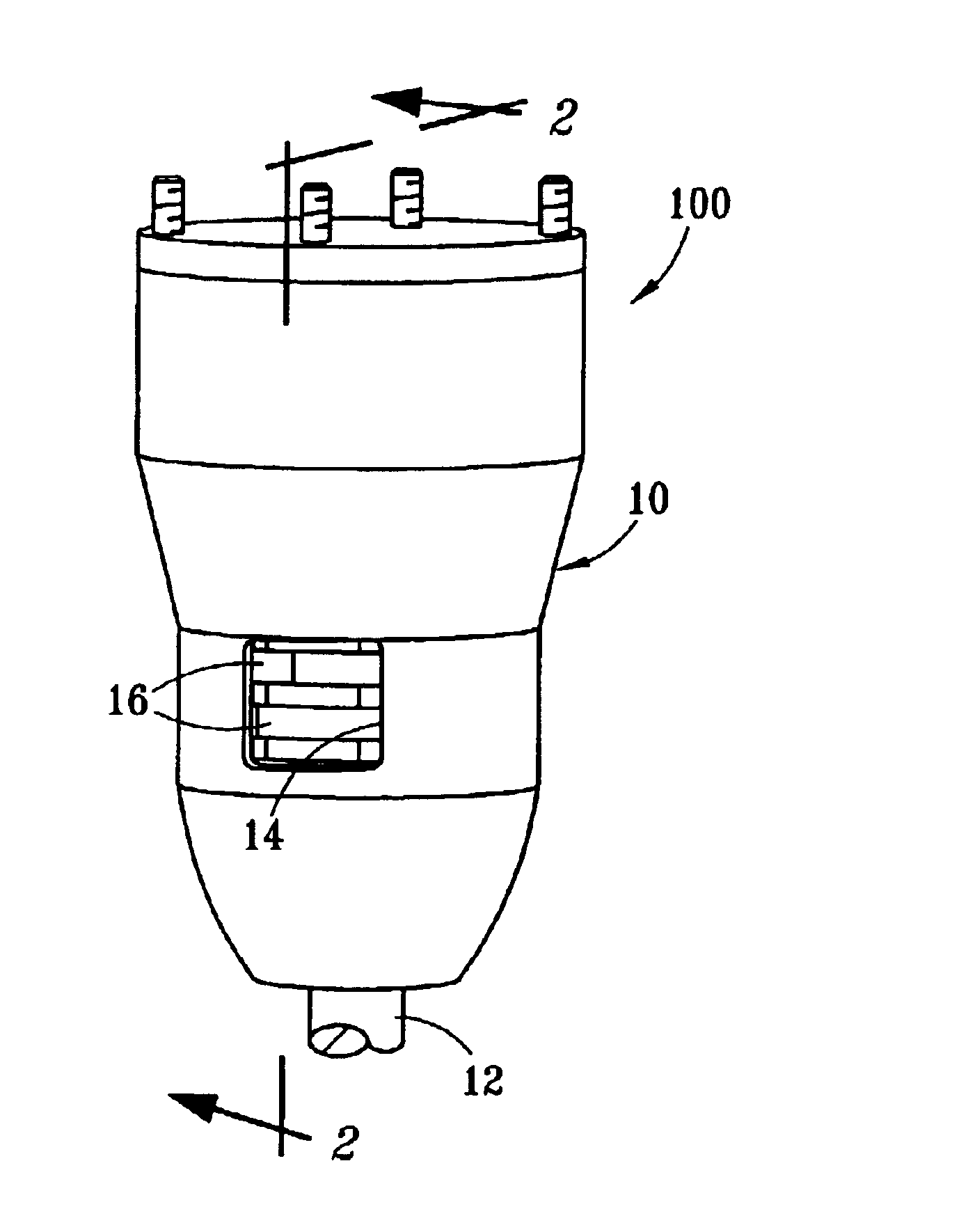
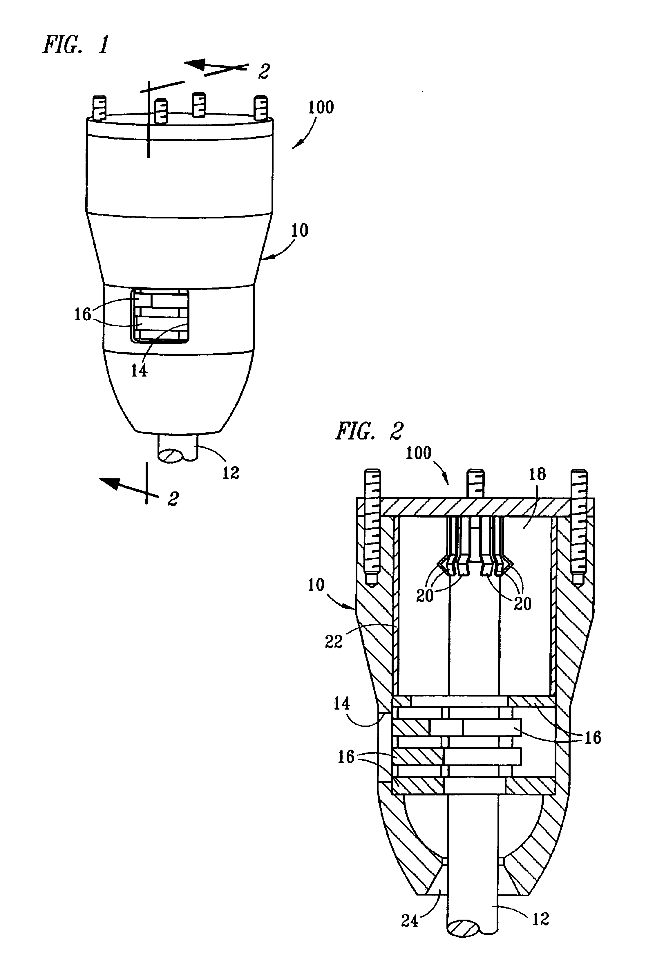
[0029]FIG. 1 shows an interrupter assembly 100 that may be used as part of a circuit breaker (not shown), for example. Interrupter assemblies generally are well-known in the art. The interrupter assembly 100 includes an interrupter shell 10 surrounding a male contact assembly 12 and a female contact assembly (not visible in FIG. 1). The interrupter shell 10 is preferably fabricated from a strong, non-conducting material such as phenolic cellulose tubing or fiberglass. The shell 10 wall is of sufficient thickness to contain the arc and to withstand the forces created by the arc-gas expansion during arcing. The interrupter assembly 10 is generally housed in an enclosure such as a tank or switch compartment, and surrounded by an insulating, non-conductive medium that may comprise oil, air, or inert gas. Also shown in FIG. 1 is an exhaust port 14 and an assembly of baffle plates 16.

[0030]In FIG. 2, a female contact assembly 18 is shown within the interrupter shell 10. The female contact...


PUM


Abstract

A fluorescent trace material is provided within at least a portion of an electrical contact or interrupter assembly component, or a cavity defined therein. At least a portion of the fluorescent trace material is exposed or released from the electrical contact or interrupter assembly component, indicating a degree of component wear.

Description

FIELD OF THE INVENTION[0001]The present invention relates in general to electrical switches and in particular to detecting the extent of erosion or wear of electrical contacts and interrupter assembly components caused by arcing or mechanical wear.BACKGROUND[0002]A variety of electrical equipment contain switches which interrupt or direct the path of electricity through an electric circuit. Circuit breakers, for example, are switches used to open a circuit in the event of a fault, or short circuit. Another type of switch is a load tap changer, which is used to automatically select a particular tap corresponding to a connection within the secondary windings of a transformer.[0003]The parts of a switch which actually perform the function of connecting and disconnecting the current path are called contacts. In high voltage equipment, the contacts of electrical switches operating under load generally erode over time during operation. The erosion of electrical contacts most commonly resu...

Claims


Application Information

Patent Timeline
IPC IPC(8): G01N21/84H01H1/00
CPCG01N21/8422H01H1/0015H01H2001/0031H01H2001/0026
Inventor NICHOLS, BRUCE
Owner NICHOLS APPLIED TECH
Why Eureka
Try Eureka