Illuminating unit for an article-sensing camera

a technology of illumination unit and article, which is applied in the field of illumination unit of article-sensing camera, can solve the problems of reducing the heat emitted by the illuminating body, and achieve the effect of accurate image-capturing of items and improved illumination quality

Inactive Publication Date: 2005-04-26
ROBERT BOSCH GMBH
View PDF12 Cites 10 Cited by
  • Summary
  • Abstract
  • Description
  • Claims
  • Application Information

AI Technical Summary

Benefits of technology

[0009]If, as noted earlier, the light-emitting diode matrix, by means of shutter control, emits light only during the image-capturing periods, a pulsed light beam results, whereby a homogenous illumination of the items may be obtained, without the items being exposed to appreciable heat stress....

Problems solved by technology

The high degree of efficiency of the light-emitting diode m...

Method used


Image

  • Illuminating unit for an article-sensing camera
  • Illuminating unit for an article-sensing camera
  • Illuminating unit for an article-sensing camera

Examples


Embodiment Construction

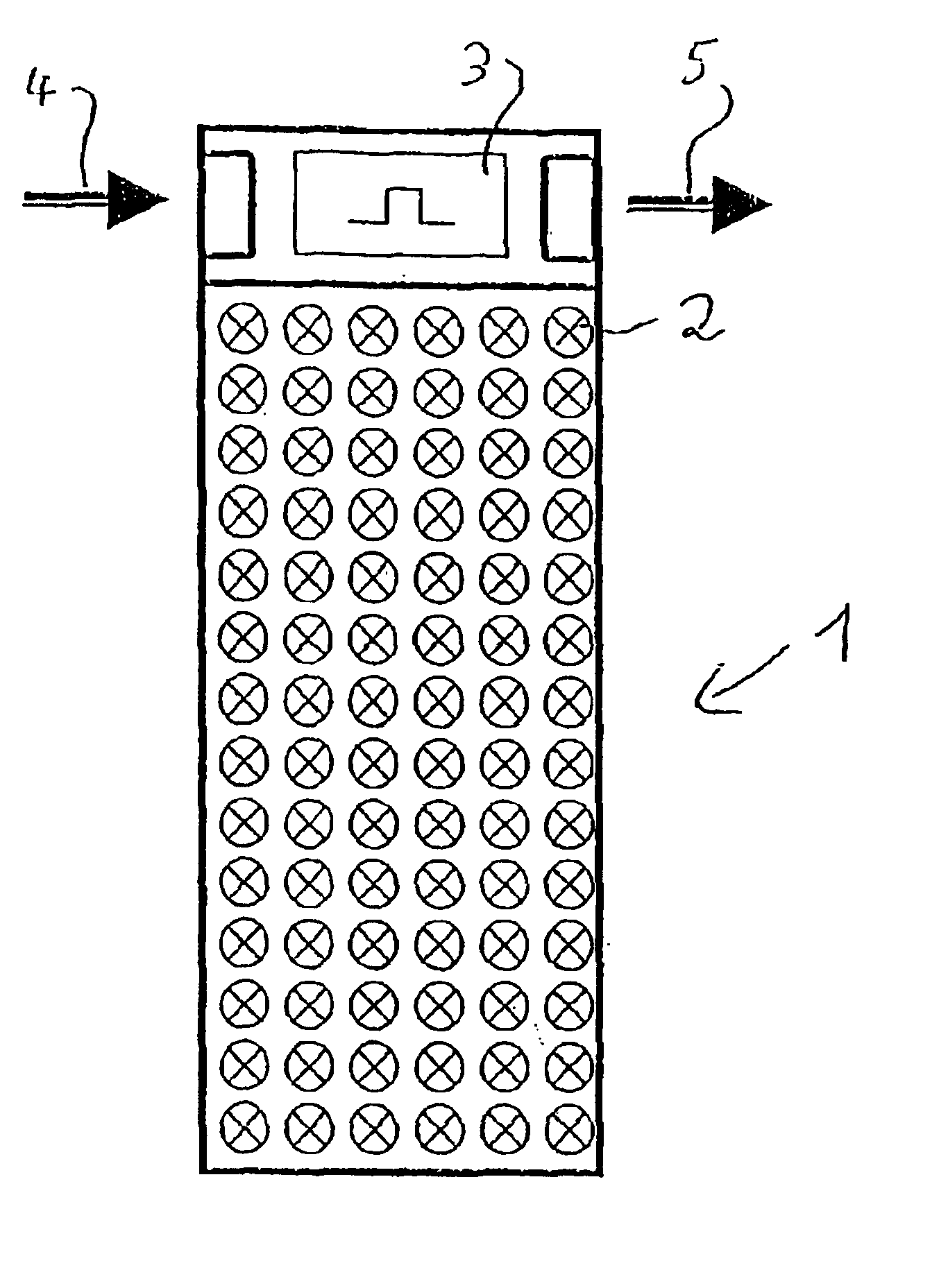
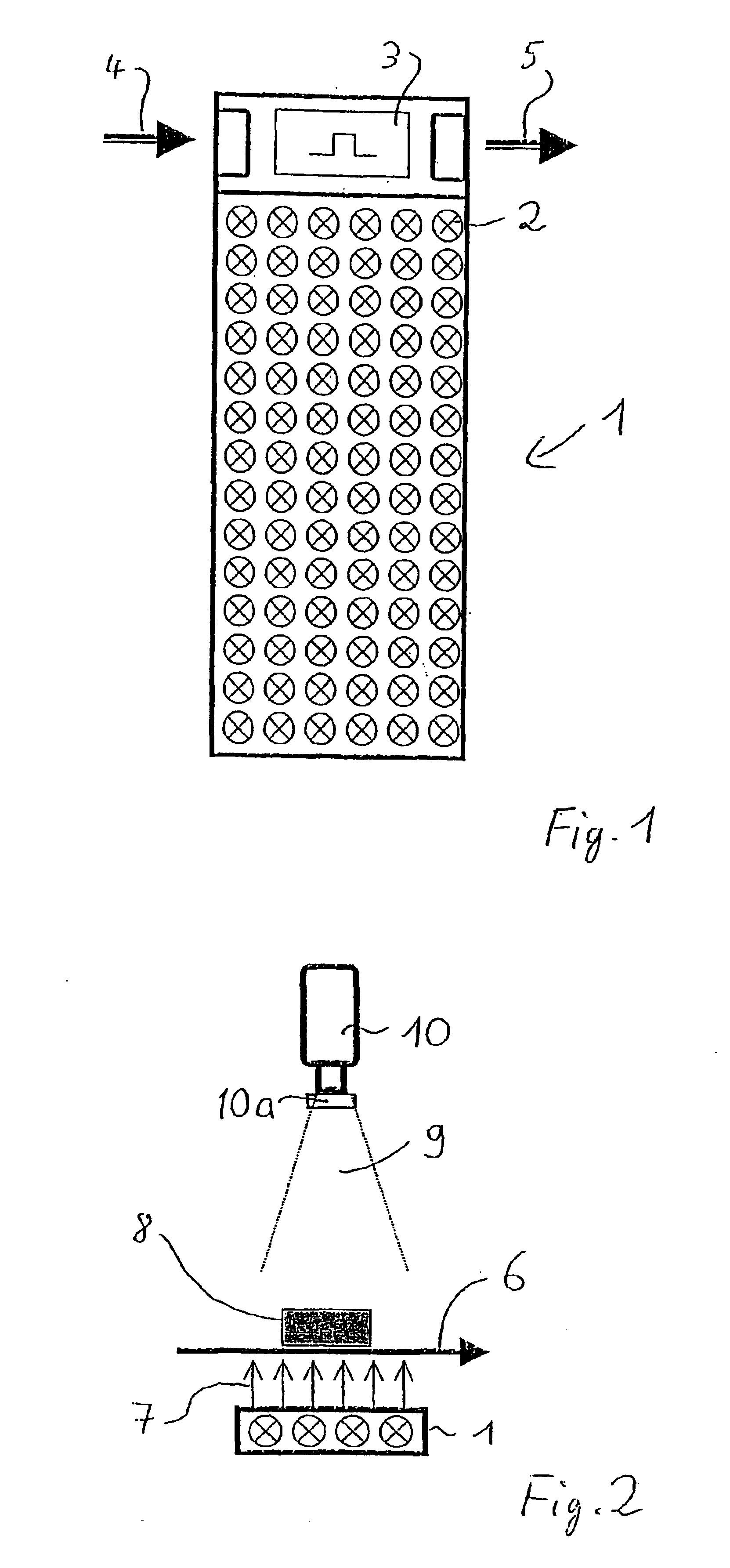
[0020]FIG. 1 shows a light-emitting diode matrix 1 composed of a plurality of light-emitting diodes 2 arranged in rows and columns. For example, there may be provided 432 light-emitting diodes arranged in 12 columns and 36 rows. The light-emitting diodes 2 as viewed together, constitute the light emitting surface. A control circuit 3 is connected to the matrix 1 which is controlled by symbolically illustrated control pulses 4 and which may forward control pulses 5 from an output to a further matrix (not shown) immediately adjoining the matrix 1 for the purpose of increasing the number of matrix columns. Thus, the matrices may be disposed in a cascade connection.

[0021]A cascade arrangement is of advantage because control pulses need to be applied only to the first matrix 1; the control pulses are then taken over by the various cascaded matrices. Such control pulses represent, in case of an intermittent operation of the matrix, the duration and timing of the energized state of the lig...


PUM


Abstract

A conveying system includes a conveyor for advancing items thereon; and an image-capturing apparatus for detecting individual items on the conveyor and for generating image signals representing an image of the items. The image-capturing apparatus includes an illuminating unit formed of a matrix composed of a plurality of light-emitting diodes; a picture-capturing unit for receiving light rays emitted by the matrix and modified by an item situated in a path of the light rays and for generating the image signals; and a control unit connected to the matrix and the picture-capturing unit for a pulsed illumination of the matrix.

Description

CROSS REFERENCE TO RELATED APPLICATION[0001]This application claims the priority of Swiss Application No. 2000 1280 / 00 filed Jun. 28, 2000, which is incorporated herein by reference.BACKGROUND OF THE INVENTION[0002]This invention relates to an apparatus for forming images of items advanced in an organized or random manner on one or several conveyors. The apparatus has at least one illuminating unit and at least one image-capturing unit (camera) associated with the illuminating unit. The image-capturing unit forms images of the items on the conveyor. The apparatus further includes a control device which controls the illuminating and image-capturing units, for example, in a manner as described in U.S. Pat. Nos. 4,972,093 and 5,936,353.[0003]An apparatus of the above-outlined type is disclosed in European Patent No. 0 856 465 which does not describe any specific illuminating device. An illumination by environmental light has the disadvantage that the reception of the line camera descri...

Claims


Application Information

Patent Timeline
IPC IPC(8): G01N21/88G03B15/00B65G43/08H01L33/00
CPCG01N21/8806
Inventor HERRE, ERWIN
Owner ROBERT BOSCH GMBH
Why Eureka
Try Eureka