Liquid crystal display device, image shifting device, and image display apparatus

a liquid crystal display and image technology, applied in the field of liquid crystal display devices and image shifting devices, can solve the problems of complicated panel designs and state-of-the-art liquid crystal display apparatuses that do not provide a sufficient response speed, so as to improve the response speed, improve the quality and the response speed of liquid crystal displays, and improve the effect of response speed

Active Publication Date: 2005-04-26
SHARP KK
View PDF9 Cites 154 Cited by
  • Summary
  • Abstract
  • Description
  • Claims
  • Application Information

AI Technical Summary

Benefits of technology

[0018]The present invention aims at realizing a liquid crystal display apparatus capable of displaying an image with a high quality and with a high response speed for various liquid crystal panels and display modes by designing the apparatus in view of the panel temperature and the temperature characteristics of the liquid crystal composition.
[0049]With the image shifting device of the present invention, it is possible to realize a high response speed by eliminating the non-uniformity in the liquid crystal response in the panel by controlling the temperature of the liquid crystal panel in an optimal temperature range. By applying the image shifting device of the present invention to an image display apparatus such as a projection type liquid crystal display apparatus, the display quality thereof can be improved.

Problems solved by technology

State-of-the-art liquid crystal display apparatuses do not provide a sufficient response speed at intermediate gray levels, whereby after-image phenomenon, and the like, are observed when displaying moving images.
However, these approaches require complicated panel designs.

Method used


Image

  • Liquid crystal display device, image shifting device, and image display apparatus
  • Liquid crystal display device, image shifting device, and image display apparatus
  • Liquid crystal display device, image shifting device, and image display apparatus

Examples


embodiment 1 (

Passive Matrix Transmission Type Liquid Crystal Display Device)

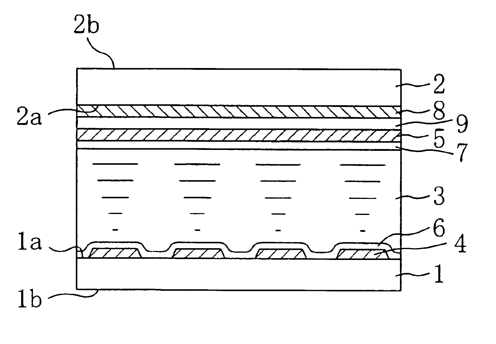
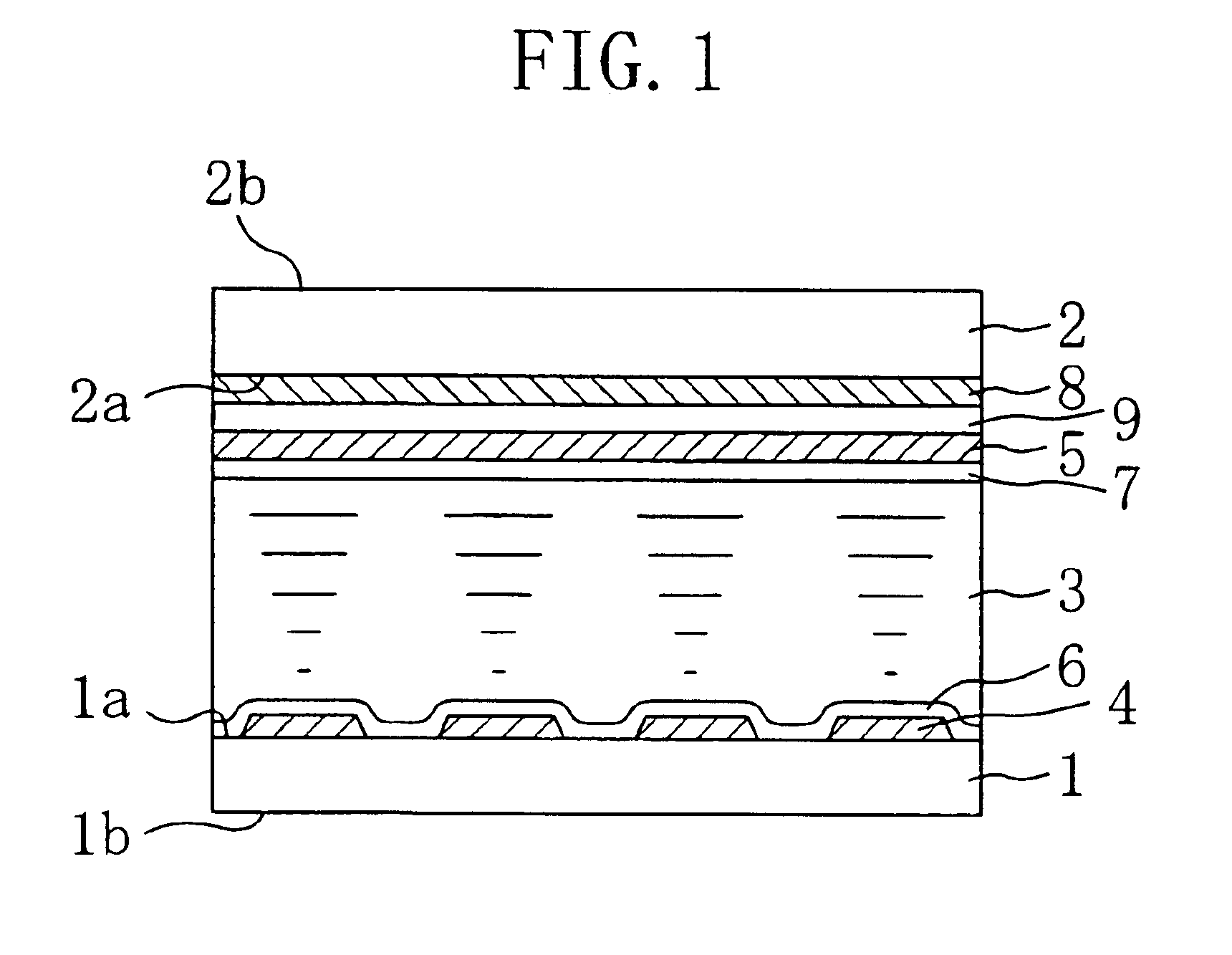
[0061]FIG. 1 is a cross-sectional view schematically illustrating a liquid crystal display device of Embodiment 1. The liquid crystal display device of the present embodiment will be described with reference to FIG. 1. The liquid crystal display device of the present embodiment is a passive matrix type liquid crystal display device, including a first substrate 1, a second substrate 2 opposing the first substrate 1, a liquid crystal layer 3 provided in the gap between the first substrate 1 and the second substrate 2, and a temperature adjustment member provided on the second substrate 2. A plurality of column electrodes 4 are provided in a stripe pattern on the first substrate 1. A plurality of row electrodes 5 perpendicular to the column electrodes 4 are provided on the second substrate 2. The column electrodes 4 and the row electrodes 5 are both display electrodes and may be made of a transparent conductive film such as...

embodiment 2 (

Active Matrix Transmission Type Liquid Crystal Display Device)

[0079]FIG. 3 is a perspective view schematically illustrating a liquid crystal display device of Embodiment 2. The liquid crystal display device of the present embodiment will be described with reference to FIG. 3. Note that in FIG. 3, those components having substantially the same functions as those of the liquid crystal display device illustrated in FIG. 1 will be denoted by the same reference numerals and will not be further described below.

[0080]The liquid crystal display device of the present embodiment includes a TFT (thin film transistor) substrate 1, a counter substrate 2 opposing the TFT substrate 1, and a TN liquid crystal layer 3 provided between the substrates 1 and 2. The TFT substrate 1 includes a plurality of gate bus lines 11 extending in the row direction, a plurality of source bus lines 12 extending perpendicular to the gate bus lines 11, TFT devices 13 each provided near an intersection between the gate...

embodiment 3 (

Projection Type Liquid Crystal Display Apparatus)

[0088]The liquid crystal display devices of Embodiments 1 and 2 can be applied to projection type liquid crystal display apparatuses (projectors) in general. In a projection type liquid crystal display apparatus, light from the light source is passed through a liquid crystal light bulb from its back side and the transmitted light is projected onto a screen through a projection lens. Embodiment 3 is directed to a three-plate projection type liquid crystal display apparatus in which three light bulbs are provided for red light, green light and blue light, respectively.

[0089]FIG. 4 is a schematic diagram illustrating a projection type liquid crystal display apparatus of the present embodiment. A projection type liquid crystal display device 1000 includes an illumination optical system 100 including a light source lamp 120, a color separation optical system 200 for separating a light beam (white light beam) from the light source lamp 120 ...


PUM

PropertyMeasurementUnit
rotational viscosity γ1aaaaaaaaaa
timeaaaaaaaaaa

Abstract

A liquid crystal display device includes a first substrate, a second substrate opposing the first substrate, a liquid crystal layer provided in a gap between the first substrate and the second substrate, and a temperature adjustment member formed on the first substrate and / or the second substrate. The panel temperature T (° C.) of the liquid crystal display device is controlled to be equal to or greater than TNI-65 and less than or equal to TNI-15, where TNI (° C.) is the nematic-isotropic phase transition temperature of the liquid crystal composition of the liquid crystal layer.

Description

[0001]This non-provisional application claims priority under 35 U.S.C. § 119(a) on Patent Application Nos. 2002-241661 and 2003-161472 filed in Japan on Aug. 22, 2002 and Jun. 6, 2003, which are herein incorporated by reference.BACKGROUND OF THE INVENTION[0002]1. Field of the Invention[0003]The present invention relates to a liquid crystal display device and an image shifting device. The liquid crystal display device and the image shifting device of the present invention can be used in an image display apparatus, e.g., a transmission type display apparatus such as a projector.[0004]2. Description of the Background ArtLiquid Crystal Display Device[0005]Japanese Laid-Open Patent Publication Nos. 2-55322 and 9-96824 disclose techniques for improving the response speed of a liquid crystal panel by increasing the temperature of the liquid crystal material with a transparent heater provided in the liquid crystal panel. With these techniques, some improvement can be expected in the respons...

Claims


Application Information

Patent Timeline
Patent Type & Authority Patents(United States)
IPC IPC(8): G02F1/133G02F1/13H04N5/74G02F1/1343G03B21/00G09F9/00
CPCG02F1/133382H04N5/7441H04N2005/745
Inventor OHNISHI, NORIAKIKUME, YASUHIRO
Owner SHARP KK
Why Eureka
Try Eureka