3-D camera for recording surface structures, in particular for dental purposes

a surface structure and camera technology, applied in the field of 3d camera for recording surface structures, can solve the problems of large unambiguous range, inability to accurately record the height difference between two object points, and poor overall measurement accuracy, so as to reduce the measurement accuracy and keep the equipment outlay low

Inactive Publication Date: 2005-04-26
SIRONA DENTAL SYSTEMS
View PDF14 Cites 291 Cited by
  • Summary
  • Abstract
  • Description
  • Claims
  • Application Information

AI Technical Summary

Benefits of technology

[0025]An object of the invention is consequently to achieve unambiguous measurements when there are large height differences, without thereby reducing the measurement accuracy and nevertheless keeping the equipment outlay low.

Problems solved by technology

Consequently, for a large period the unambiguous range is large, although the height difference between two object points cannot be recorded so accurately.
A disadvantage with this that either superposition of the first grating on the second is necessary, with the result that poorer measurement accuracy is achieved on the whole, or a long recording time is necessary.
A disadvantage with this is that the equipment outlay is large precisely for manually operated 3-D cameras, and a device which is easy to handle can therefore only be produced with difficulty.
This disadvantage also arises with WO 98 / 11 403 A1, which discloses a process and a device for the three-dimensional measurement of objects by optical recording, projected patterns and triangulation calculations, in which the projection unit for the pattern and the recording unit are constructed separately from one another and can be positioned or introduced in the course of the measurement process independently of one another.

Method used


Image

  • 3-D camera for recording surface structures, in particular for dental purposes
  • 3-D camera for recording surface structures, in particular for dental purposes

Examples


Embodiment Construction

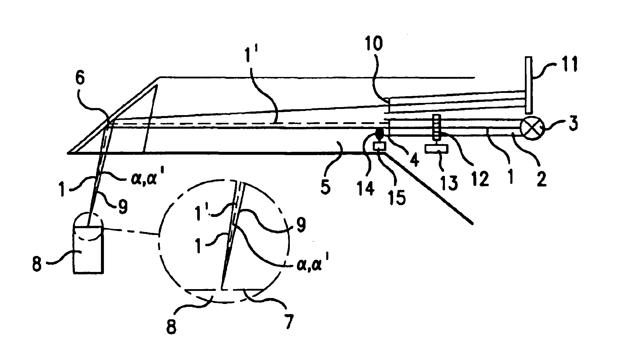
[0032]The present invention provides a 3-D camera for recording surface structures on an object of interest by means of triangulation, in particular for dental purposes, having means for producing a group of light beams in order to illuminate the object of interest via a projection optical path, an image sensor for receiving light back-scattered by the object of interest via an observation optical path, and having means in the projection optical path for producing a pattern projected onto the object of interest.

[0033]According to the invention, the 3-D camera contains means in the projection optical path and / or the observation optical path for altering the triangulation angle, which is defined by the angle between the centroid beam of the projection optical path and the centroid beam of the observation optical path.

[0034]The means for altering the triangulation angle bring about an alteration to the centroid beam of the projection and / or observation optical path. By providing these ...


PUM


Abstract

A 3-D camera and a method for recording surface structures on an object of interest by triangulation, in particular for dental purposes. The camera provides for producing a group of light beams in order to illuminate the object of interest via a projection optical path, an image sensor for receiving light back-scattered by the object of interest via an observation optical path, and provides, in the projection optical path, for producing a pattern projected onto the object of interest. To avoid ambiguities in the event of large height differences, the camera provides for the projection optical path and / or the observation optical path for altering the triangulation angle, which is defined by the angle between the centroid beam of the projection optical path and the centroid beam of the observation optical path. The proposed process involves the taking of at least two 3-D measurements of the same object of interest with different triangulation angles.

Description

BACKGROUND OF THE INVENTION[0001]1. Field of the Invention[0002]The invention relates to a 3-D camera for recording surface structures on an object of interest by means of triangulation, in particular for dental purposes.[0003]2. Relevant Prior Art[0004]3-D cameras (i.e., cameras for recording three-dimensional structures) for dental applications mostly serve the purpose of recording the surface structure of a tooth in the mouth of a patient. Therefore, they must fulfil several requirements such as the possibility of using the camera “endoscopically” in the mouth of the patient, the possibility of placing the camera in the mouth manually, and a measuring time short enough to avoid blurring even if the camera is used without further fixation. It should further be possible to record the complete surface structure if possible in a single exposure, at a maximum in two exposures. It is therefore important that the results of the measurement are displayed to the operator as shortly as pos...

Claims


Application Information

Patent Timeline
Patent Type & Authority Patents(United States)
IPC IPC(8): A61C9/00A61B5/107A61C19/04G01B11/24G01C3/06G03B35/00H04N13/02
CPCA61B5/0064A61B5/0088A61B5/1077A61C9/00G01B11/2527G01B11/0608G01B11/24G01B11/2513A61C9/004A61C9/0053
Inventor PFEIFFER, JOACHIMSCHWOTZER, AXEL
Owner SIRONA DENTAL SYSTEMS
Why Eureka
Try Eureka