Drive unit with an internal combustion engine and an exhaust gas turbocharger

a technology of internal combustion engine and drive unit, which is applied in the direction of braking system, fluid gearing, coupling, etc., can solve the problem that the drive unit does not contribute directly to the braking in braking mod

Inactive Publication Date: 2005-05-03
VOITH TURBO GMBH & CO KG
View PDF11 Cites 21 Cited by
  • Summary
  • Abstract
  • Description
  • Claims
  • Application Information

AI Technical Summary

Benefits of technology

[0007]Accordingly, the hydrodynamic unit is configured in a particular way with the two turbine blades. The two turbine blades are in fact configured and arranged in such a way that they can operate as rotors. Here, their structure is basically the same as that of turbine blades of a hydrodynamic clutch or of a retarder. The difference with respect to a hydr...

Problems solved by technology

However, said drive units do not contri...

Method used


Image

  • Drive unit with an internal combustion engine and an exhaust gas turbocharger
  • Drive unit with an internal combustion engine and an exhaust gas turbocharger
  • Drive unit with an internal combustion engine and an exhaust gas turbocharger

Examples


first embodiment

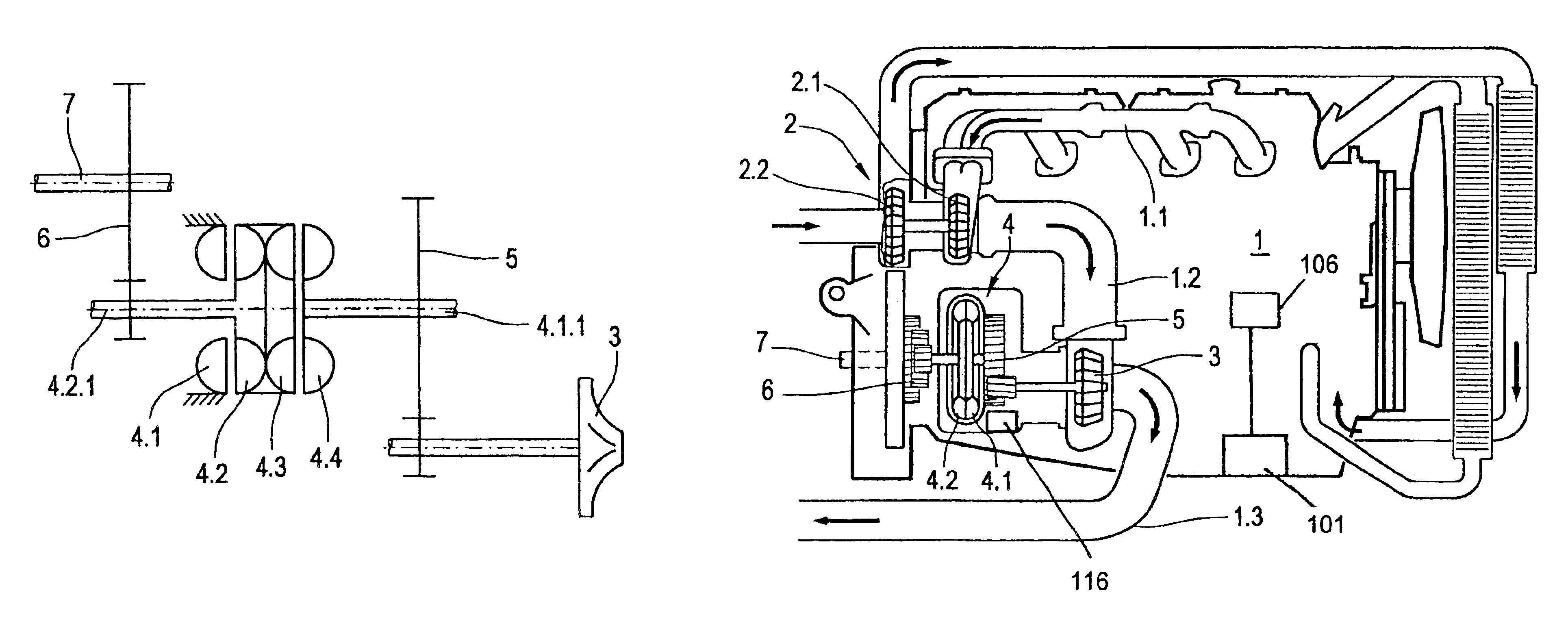
[0017]The drive unit which is illustrated schematically in FIG. 1 comprises an exhaust gas turbine 3. The exhaust gas stream of an engine (not shown here) is applied to said exhaust gas turbine 3. The exhaust gas turbine 3 is however not a component of an exhaust gas turbocharger. An exhaust gas turbocharger may be connected upstream of the aforesaid exhaust gas turbine 3.

[0018]A hydrodynamic unit 4 is also shown. Said hyrodynamic unit 4 has a primary turbine wheel 4.1 and a secondary turbine wheel 4.2. The two turbine wheels are configured like the turbine wheels of a hydrodynamic clutch or of a hydrodynamic brake. However, both turbine wheels are basically freely rotatable. A parking brake 4.5 is assigned to the primary wheel 4.1. In this way the primary wheel 4.1 can be locked.

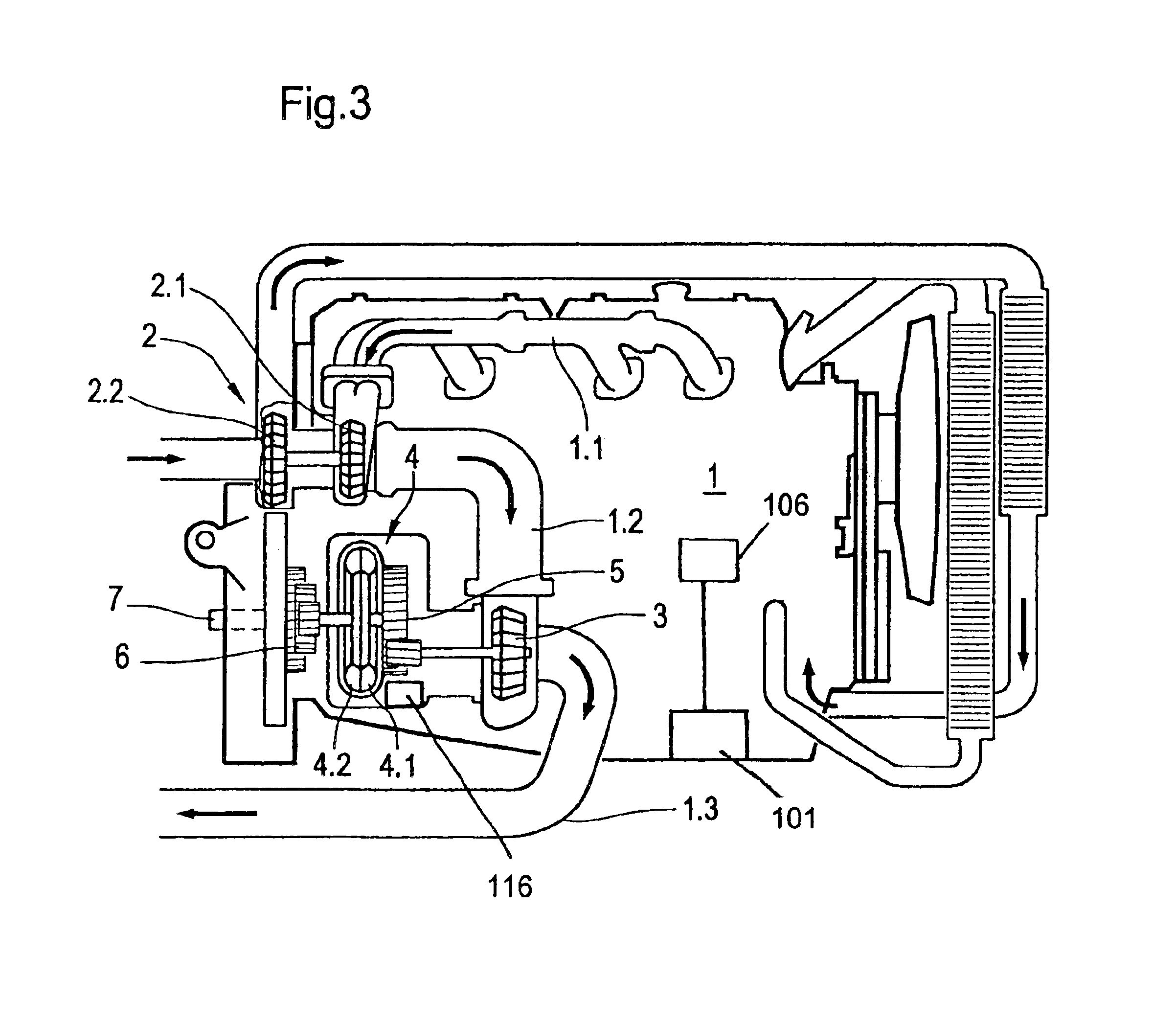
[0019]A sensor 101 may be provided to sense the operating state of the engine (i.e., normal mode or braking mode) and supply a corresponding signal to a central process unit 106. The central processor unit...

second embodiment

[0028]The drive unit of the second embodiment operates as follows:

In the traction mode, the working space of the retarder 4.1, 4.2 is empty, while the working space of the clutch 4.3, 4.4 is filled with a working medium, generally an oil.

[0029]An exhaust gas stream is applied to the exhaust gas turbine 3 from the internal combustion engine (not illustrated here). The exhaust gas turbine 3 drives the first gear train 5 via the shaft 3.1, and the shaft 4.1.1 drives the primary wheel 4.4 of the clutch. Said primary wheel 4.4 transmits torque to the tandem unit, formed from the secondary wheel 4.3 of the clutch and the wheel 4.2 of the retarder. These two wheels are connected to one another fixed in terms of rotation and form what is referred to as a back-to-back unit. From there, torque is transmitted onward via the shaft 4.2.1 and the second gear train 6 to the crankshaft 7.

[0030]During the braking mode, the working space of the retarder 4.1, 4.2 is filled. The working space of the hy...


PUM


Abstract

The invention relates to a drive unit, comprising an internal combustion engine with a crankshaft; an exhaust line; an exhaust gas turbine which is acted on by the exhaust gas line, which is arranged downstream of the internal combustion engine and has the purpose of transmitting a positive torque to the crankshaft in the traction mode; a hydrodynamic unit which is arranged downstream of the exhaust gas turbine and has two turbine blades which form a torus-shaped working chamber; the hydrodynamic unit has a drive connection to the drive train; and a parking brake is provided for securing the primary turbine wheel of the exhaust gas turbine.

Description

FIELD OF THE INVENTION[0001]The invention relates to a drive unit comprising an internal combustion engine.BACKGROUND[0002]DE 195 16 97 describes a drive unit having an internal combustion engine having turbocompound design. In this unit, a turbine is provided to which exhaust gas is fed from the internal combustion engine during the traction mode in order to drive the turbine. The turbine has a drive connection to the crankshaft via a hydrodynamic clutch. In this way it is possible to utilize the residual energy still present in the exhaust gas.[0003]In the aforesaid drive unit, a further exhaust line is connected downstream of the turbine. An exhaust valve is provided in this exhaust line. At the changeover from the traction mode to the braking mode, the exhaust valve is closed. As a result, an exhaust gas pressure which causes the exhaust valve to open when a certain value is reached builds up behind the turbine.[0004]DE 37 28 681 C2 and DE 39 04 399 A1 also describe drive units ...

Claims


Application Information

Patent Timeline
IPC IPC(8): B60T1/00B60T1/08B60T1/06F02B37/10F02B37/00F02B41/10F02B37/04F02B41/00F01N5/04F16D33/16F16H47/10
CPCB60T1/062F02B37/005F02B37/105F02B41/10B60W10/196F16D57/04F16D67/02B60T10/02Y02T10/144F16D33/00Y02T10/163Y02T10/12
Inventor FRIEDRICH, JURGENHEILINGER, PETERKAMOSSA, KAI
Owner VOITH TURBO GMBH & CO KG
Why Eureka
Try Eureka