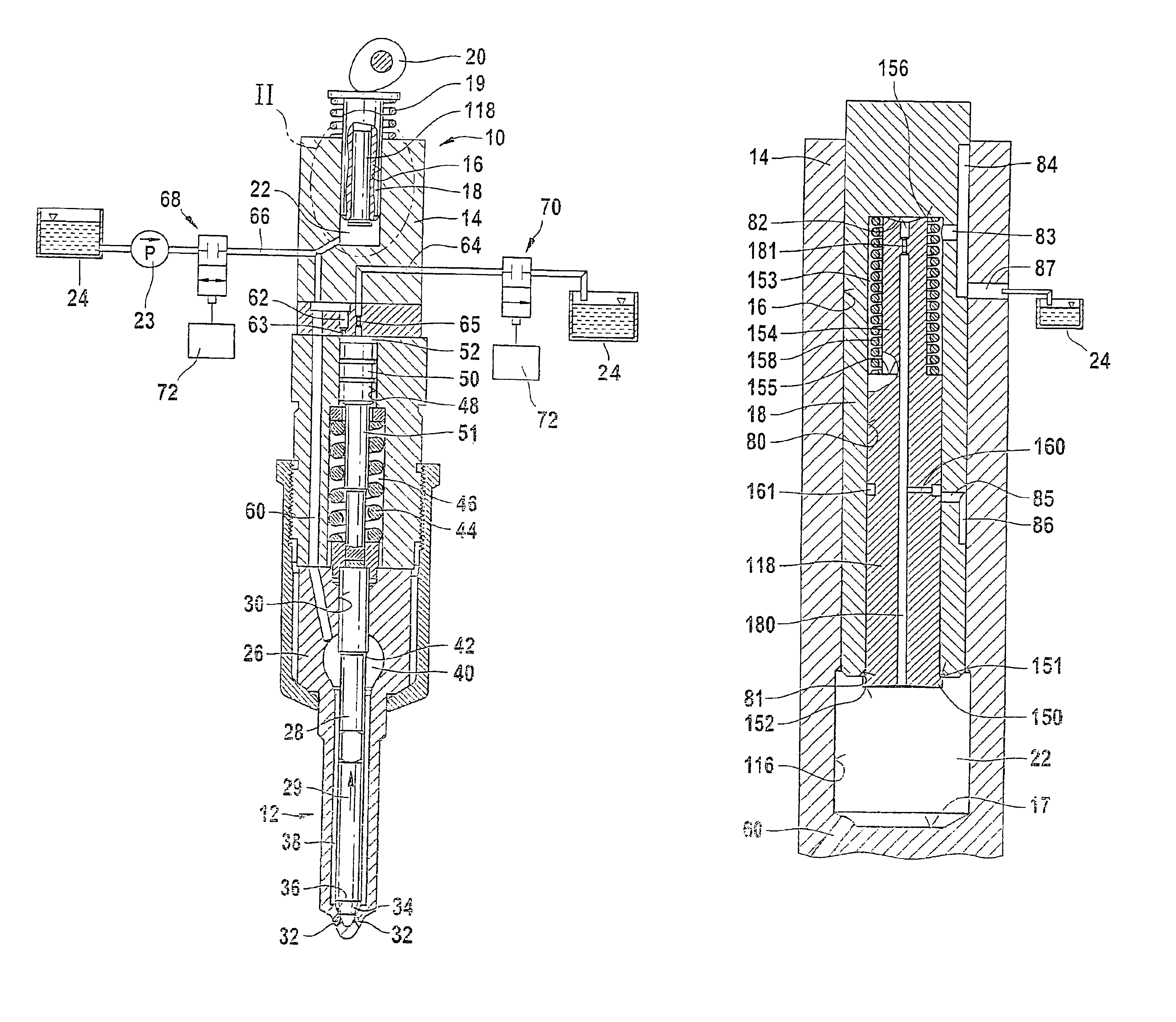
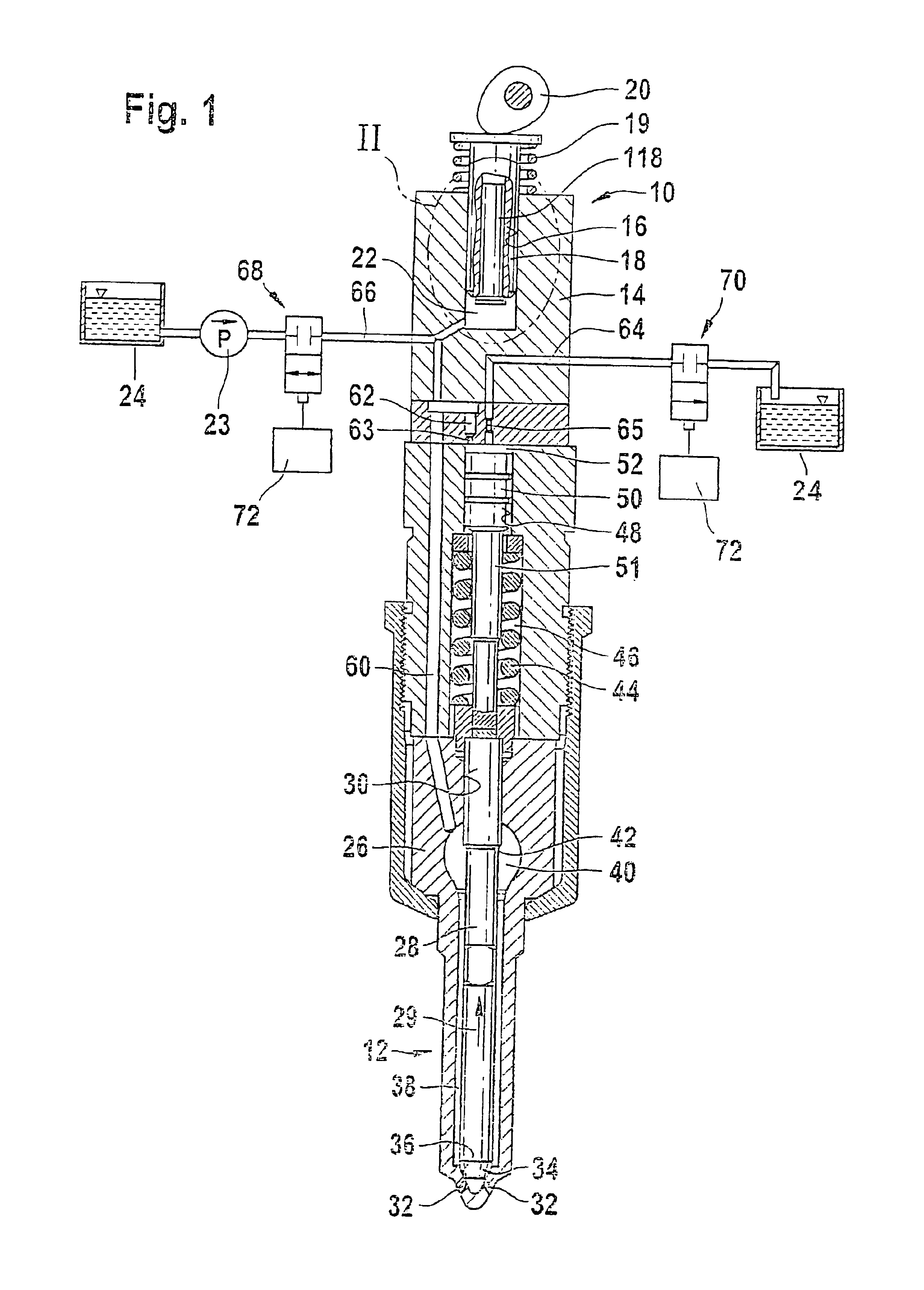
[0006]The fuel injection apparatus according to the invention has the advantage over the prior art that the pressure produced by the high-pressure pump can be limited by bringing the second pump piston into a passive position so that only the first pump piston continues to supply fuel. It is possible for the two pump pistons to be coupled to each other so that they execute a joint delivery stroke at a low engine speed, while at a high engine speed, the second pump piston is placed into its passive position so that only the first pump piston executes a delivery stroke, thus reducing the pressure produced. The first pump piston can be embodied with a diameter great enough that a high pressure is produced even at a low engine speed.
[0003]The invention is directed to an improved fuel injection apparatus for an internal combustion engine.
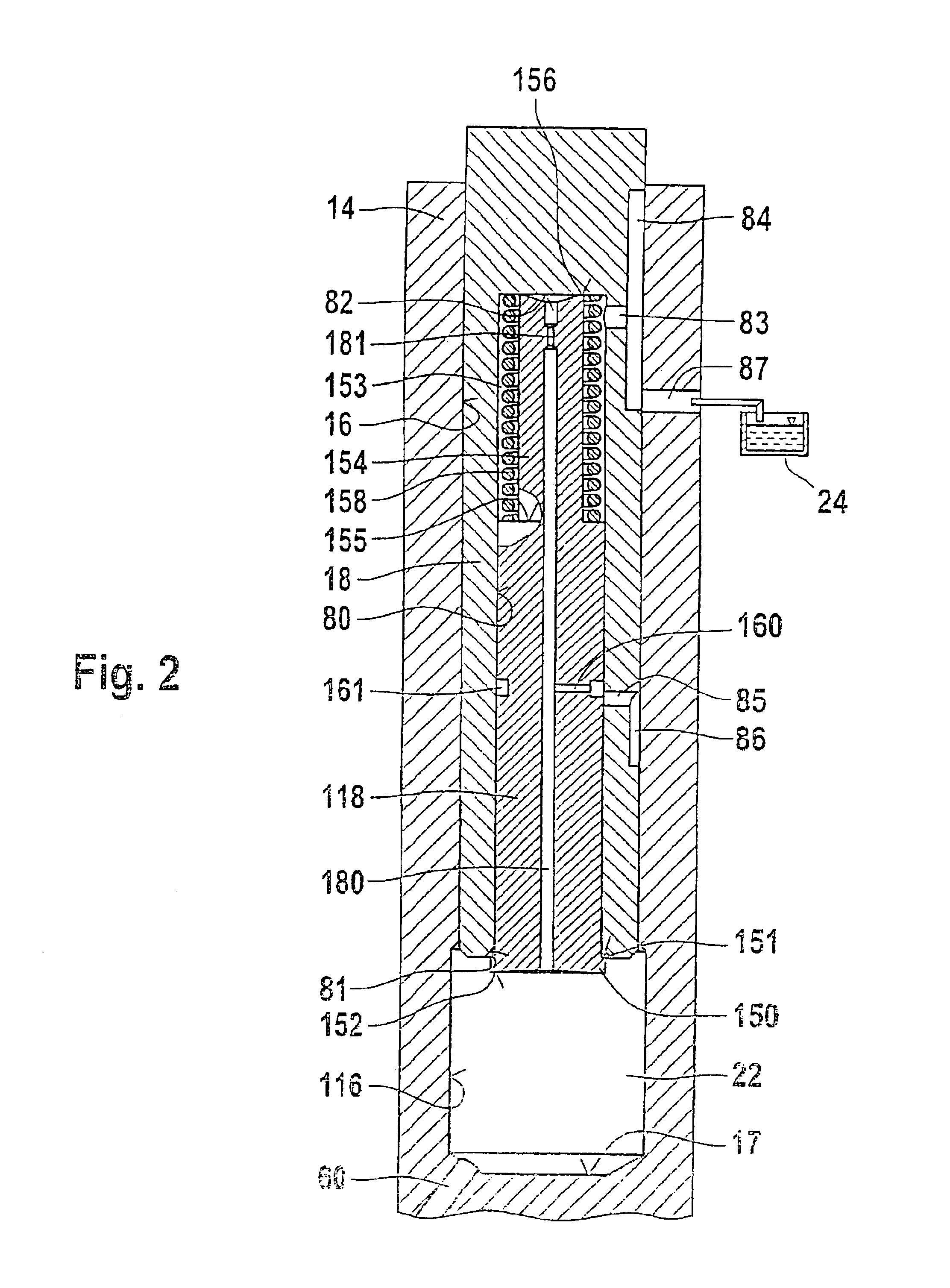
[0007]Advantageous embodiments and modifications of the fuel injection apparatus according to the invention are disclosed. One embodiment permits an advantageous placement of the second pump piston into its passive position, while another makes it possible for the pump piston to be easily manufactured. A further embodiment permits a pressure compensation between the pump working chamber and the chamber in the first pump piston in the event of a leak. It can assured that when the pump pistons are coupled to each other, no fuel can flow out of the pump working chamber via the through bore in the second pump piston, and a contact of the second pump piston against the extremity of the pump working chamber in the region of the inner dead center of the pump piston. One embodiment assures that when the second pump piston is disposed in its passive position during the delivery stroke of the first pump piston, no fuel can flow out of the pump working chamber via the through bore in the second pump piston, while another embodiment achieves a pressure compensation between the through bore in the second pump piston and the pump working chamber when in the vicinity of the inner dead center of the pump pistons. Another embodiment achieves a reliable contact of the second pump piston against the extremity, while still another achieves a simple placement of the second pump piston into its passive position.
[0006]The fuel injection apparatus according to the invention has the advantage over the prior art that the pressure produced by the high-pressure pump can be limited by bringing the second pump piston into a passive position so that only the first pump piston continues to supply fuel. It is possible for the two pump pistons to be coupled to each other so that they execute a joint delivery stroke at a low engine speed, while at a high engine speed, the second pump piston is placed into its passive position so that only the first pump piston executes a delivery stroke, thus reducing the pressure produced. The first pump piston can be embodied with a diameter great enough that a high pressure is produced even at a low engine speed.
[0007]Advantageous embodiments and modifications of the fuel injection apparatus according to the invention are disclosed. One embodiment permits an advantageous placement of the second pump piston into its passive position, while another makes it possible for the pump piston to be easily manufactured. A further embodiment permits a pressure compensation between the pump working chamber and the chamber in the first pump piston in the event of a leak. It can assured that when the pump pistons are coupled to each other, no fuel can flow out of the pump working chamber via the through bore in the second pump piston, and a contact of the second pump piston against the extremity of the pump working chamber in the region of the inner dead center of the pump piston. One embodiment assures that when the second pump piston is disposed in its passive position during the delivery stroke of the first pump piston, no fuel can flow out of the pump working chamber via the through bore in the second pump piston, while another embodiment achieves a pressure compensation between the through bore in the second pump piston and the pump working chamber when in the vicinity of the inner dead center of the pump pistons. Another embodiment achieves a reliable contact of the second pump piston against the extremity, while still another achieves a simple placement of the second pump piston into its passive position.
[0007]Advantageous embodiments and modifications of the fuel injection apparatus according to the invention are disclosed. One embodiment permits an advantageous placement of the second pump piston into its passive position, while another makes it possible for the pump piston to be easily manufactured. A further embodiment permits a pressure compensation between the pump working chamber and the chamber in the first pump piston in the event of a leak. It can assured that when the pump pistons are coupled to each other, no fuel can flow out of the pump working chamber via the through bore in the second pump piston, and a contact of the second pump piston against the extremity of the pump working chamber in the region of the inner dead center of the pump piston. One embodiment assures that when the second pump piston is disposed in its passive position during the delivery stroke of the first pump piston, no fuel can flow out of the pump working chamber via the through bore in the second pump piston, while another embodiment achieves a pressure compensation between the through bore in the second pump piston and the pump working chamber when in the vicinity of the inner dead center of the pump pistons. Another embodiment achieves a reliable contact of the second pump piston against the extremity, while still another achieves a simple placement of the second pump piston into its passive position.
[0007]Advantageous embodiments and modifications of the fuel injection apparatus according to the invention are disclosed. One embodiment permits an advantageous placement of the second pump piston into its passive position, while another makes it possible for the pump piston to be easily manufactured. A further embodiment permits a pressure compensation between the pump working chamber and the chamber in the first pump piston in the event of a leak. It can assured that when the pump pistons are coupled to each other, no fuel can flow out of the pump working chamber via the through bore in the second pump piston, and a contact of the second pump piston against the extremity of the pump working chamber in the region of the inner dead center of the pump piston. One embodiment assures that when the second pump piston is disposed in its passive position during the delivery stroke of the first pump piston, no fuel can flow out of the pump working chamber via the through bore in the second pump piston, while another embodiment achieves a pressure compensation between the through bore in the second pump piston and the pump working chamber when in the vicinity of the inner dead center of the pump pistons. Another embodiment achieves a reliable contact of the second pump piston against the extremity, while still another achieves a simple placement of the second pump piston into its passive position.
[0007]Advantageous embodiments and modifications of the fuel injection apparatus according to the invention are disclosed. One embodiment permits an advantageous placement of the second pump piston into its passive position, while another makes it possible for the pump piston to be easily manufactured. A further embodiment permits a pressure compensation between the pump working chamber and the chamber in the first pump piston in the event of a leak. It can assured that when the pump pistons are coupled to each other, no fuel can flow out of the pump working chamber via the through bore in the second pump piston, and a contact of the second pump piston against the extremity of the pump working chamber in the region of the inner dead center of the pump piston. One embodiment assures that when the second pump piston is disposed in its passive position during the delivery stroke of the first pump piston, no fuel can flow out of the pump working chamber via the through bore in the second pump piston, while another embodiment achieves a pressure compensation between the through bore in the second pump piston and the pump working chamber when in the vicinity of the inner dead center of the pump pistons. Another embodiment achieves a reliable contact of the second pump piston against the extremity, while still another achieves a simple placement of the second pump piston into its passive position.
[0007]Advantageous embodiments and modifications of the fuel injection apparatus according to the invention are disclosed. One embodiment permits an advantageous placement of the second pump piston into its passive position, while another makes it possible for the pump piston to be easily manufactured. A further embodiment permits a pressure compensation between the pump working chamber and the chamber in the first pump piston in the event of a leak. It can assured that when the pump pistons are coupled to each other, no fuel can flow out of the pump working chamber via the through bore in the second pump piston, and a contact of the second pump piston against the extremity of the pump working chamber in the region of the inner dead center of the pump piston. One embodiment assures that when the second pump piston is disposed in its passive position during the delivery stroke of the first pump piston, no fuel can flow out of the pump working chamber via the through bore in the second pump piston, while another embodiment achieves a pressure compensation between the through bore in the second pump piston and the pump working chamber when in the vicinity of the inner dead center of the pump pistons. Another embodiment achieves a reliable contact of the second pump piston against the extremity, while still another achieves a simple placement of the second pump piston into its passive position.
[0007]Advantageous embodiments and modifications of the fuel injection apparatus according to the invention are disclosed. One embodiment permits an advantageous placement of the second pump piston into its passive position, while another makes it possible for the pump piston to be easily manufactured. A further embodiment permits a pressure compensation between the pump working chamber and the chamber in the first pump piston in the event of a leak. It can assured that when the pump pistons are coupled to each other, no fuel can flow out of the pump working chamber via the through bore in the second pump piston, and a contact of the second pump piston against the extremity of the pump working chamber in the region of the inner dead center of the pump piston. One embodiment assures that when the second pump piston is disposed in its passive position during the delivery stroke of the first pump piston, no fuel can flow out of the pump working chamber via the through bore in the second pump piston, while another embodiment achieves a pressure compensation between the through bore in the second pump piston and the pump working chamber when in the vicinity of the inner dead center of the pump pistons. Another embodiment achieves a reliable contact of the second pump piston against the extremity, while still another achieves a simple placement of the second pump piston into its passive position.
[0007]Advantageous embodiments and modifications of the fuel injection apparatus according to the invention are disclosed. One embodiment permits an advantageous placement of the second pump piston into its passive position, while another makes it possible for the pump piston to be easily manufactured. A further embodiment permits a pressure compensation between the pump working chamber and the chamber in the first pump piston in the event of a leak. It can assured that when the pump pistons are coupled to each other, no fuel can flow out of the pump working chamber via the through bore in the second pump piston, and a contact of the second pump piston against the extremity of the pump working chamber in the region of the inner dead center of the pump piston. One embodiment assures that when the second pump piston is disposed in its passive position during the delivery stroke of the first pump piston, no fuel can flow out of the pump working chamber via the through bore in the second pump piston, while another embodiment achieves a pressure compensation between the through bore in the second pump piston and the pump working chamber when in the vicinity of the inner dead center of the pump pistons. Another embodiment achieves a reliable contact of the second pump piston against the extremity, while still another achieves a simple placement of the second pump piston into its passive position.
[0007]Advantageous embodiments and modifications of the fuel injection apparatus according to the invention are disclosed. One embodiment permits an advantageous placement of the second pump piston into its passive position, while another makes it possible for the pump piston to be easily manufactured. A further embodiment permits a pressure compensation between the pump working chamber and the chamber in the first pump piston in the event of a leak. It can assured that when the pump pistons are coupled to each other, no fuel can flow out of the pump working chamber via the through bore in the second pump piston, and a contact of the second pump piston against the extremity of the pump working chamber in the region of the inner dead center of the pump piston. One embodiment assures that when the second pump piston is disposed in its passive position during the delivery stroke of the first pump piston, no fuel can flow out of the pump working chamber via the through bore in the second pump piston, while another embodiment achieves a pressure compensation between the through bore in the second pump piston and the pump working chamber when in the vicinity of the inner dead center of the pump pistons. Another embodiment achieves a reliable contact of the second pump piston against the extremity, while still another achieves a simple placement of the second pump piston into its passive position.
[0006]The fuel injection apparatus according to the invention has the advantage over the prior art that the pressure produced by the high-pressure pump can be limited by bringing the second pump piston into a passive position so that only the first pump piston continues to supply fuel. It is possible for the two pump pistons to be coupled to each other so that they execute a joint delivery stroke at a low engine speed, while at a high engine speed, the second pump piston is placed into its passive position so that only the first pump piston executes a delivery stroke, thus reducing the pressure produced. The first pump piston can be embodied with a diameter great enough that a high pressure is produced even at a low engine speed.

