Combustion-powered driving tool

a driving tool and combustion technology, applied in the direction of manufacturing tools, stapling tools, nailing tools, etc., can solve the problems of low driving force, low efficiency, and high cost of methods, and achieve the effect of convenient use, low cost and high efficiency

Inactive Publication Date: 2005-05-03
KOKI HLDG CO LTD
View PDF8 Cites 671 Cited by
  • Summary
  • Abstract
  • Description
  • Claims
  • Application Information

AI Technical Summary

Benefits of technology

[0015]In view of the foregoing, it is an object of the present invention to provide a combustion-powered tool that is cheaper and more efficient and user-friendly than the combustion-powered tool of the prior art.
[0016]It is another object of the present invention to provide a combustion-powered tool that can be used for a long period of time without replacing a gas tank.
[0022]According to another aspect of the invention, there is provided a combustion-powered driving tool for driving fasteners into a workpiece, that includes a housing, a head section, a motor, a battery, a power source section, a motor drive controlling section, a first switch, a second switch, a cylinder, a piston, a combustion chamber frame, a fan, a sparkplug, and a controller. The head section seals one end of the housing and has a flammable gas channel formed therein. The power source section is supplied with the operating voltage of the battery and generates a reference voltage. The motor drive controlling section is supplied with the operating voltage of the battery and the reference voltage from the power source section and drives the motor based on the operating voltage and the reference voltage. The first switch detects whether the tool is pressed against the workpiece and outputs a first signal indicative of a detected condition. The second switch instructs driving the fastener into the workpiece and outputs a second signal indicative of an instruction to drive the fastener. The combustion chamber frame moves to contact and separate from the head section and forms a combustion chamber together with the head section, the cylinder, and the piston when the combustion chamber frame is in contact with the head section. The fan is rotatably disposed in the combustion chamber and driven to rotate by the motor. The sparkplug is exposed in the combustion chamber for igniting a mixture of air and flammable gas in the combustion chamber. The flammable gas is supplied into the combustion chamber via the flammable gas channel, wherein explosive combustion caused by firing of the sparkplug moves the piston toward the second end of the housing and a fastener is driven into the workpiece in accordance with the movement of the piston. The controller controls the power source section so as not to generate the reference voltage in order to reduce power consumption when at least one of the first signal and the second signal indicates that the tool is left unused for a prescribed period of time. The controller may further control the power source section so as not to generate the reference voltage in order to reduce power consumption when at least one of the first signal and the second signal indicates that at least one of the first switch and the second switch malfunctions.

Problems solved by technology

If the trigger switch is operated at this time, the spark plug ignites the gas-air mixture, causing explosive combustion.
(1) Pressing the push lever against the workpiece switches on a head switch (or push switch). The head switch (or push switch) actuates the motor, which drives the fan to rotate. When the user operates the trigger switch, the spark plug fires, igniting the gas-air mixture. However, if the trigger switch is operated in a relatively short time period after the motor and the fan begin to rotate, the motor and fan have not yet reached a rotational speed capable of producing a sufficient driving force. In such cases, a low driving force is produced.
However, these methods are expensive and greatly reduce work efficiency and user-friendliness.
(3) When the tool is used under a low temperature circumstance, the liquefied gas injected into the combustion chamber is not sufficiently vaporized and thus cannot be mixed with air.
However, repeated injection of the liquefied gas consumes the gas in vain and the duration of time the tool is continuously usable with the loaded gas tank is shortened.
(4) Because a high voltage is applied to an electric circuit accommodated in the tool and a large current is flowing therein when the tool is operating, a voltage caused by noises is induced on the wiring of the tool, which prevents the tool from operating normally.

Method used


Image

  • Combustion-powered driving tool
  • Combustion-powered driving tool
  • Combustion-powered driving tool

Examples


first embodiment

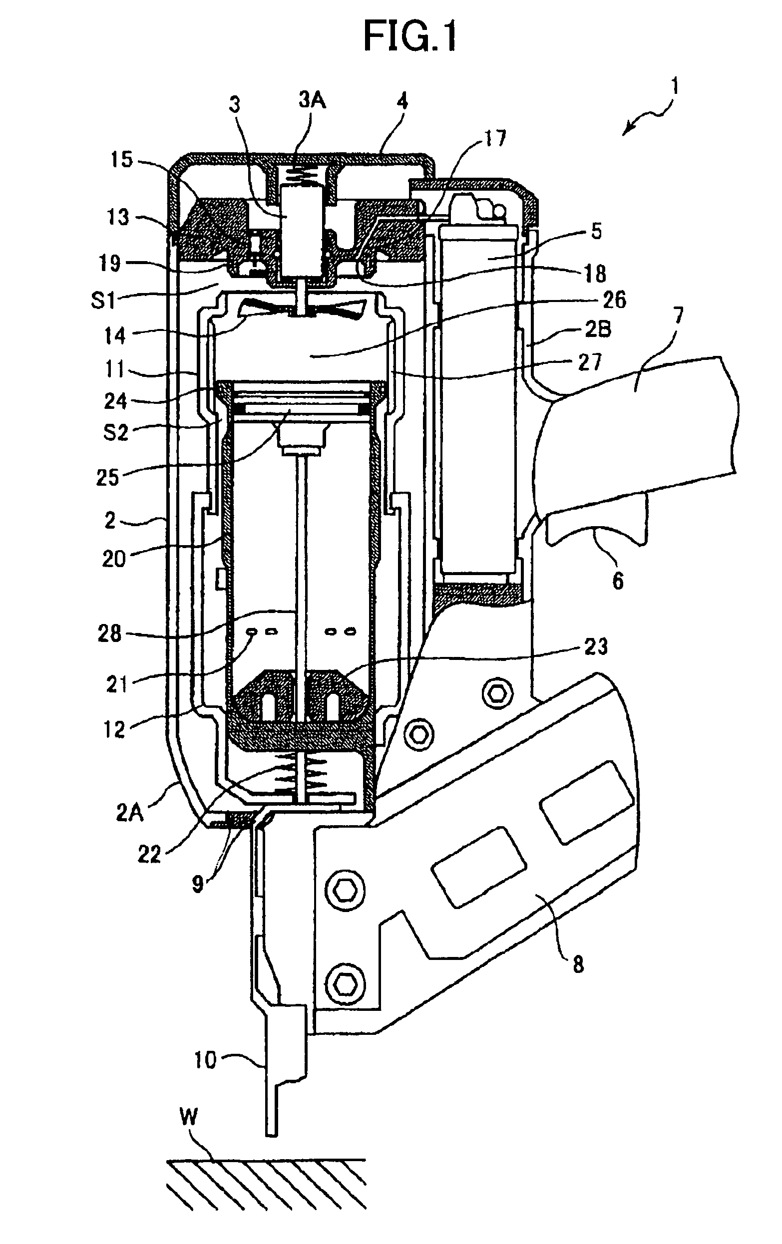
[0038]Next, a first embodiment will be described while referring to FIGS. 1, 2 and 3A–3B, wherein the combustion-powered tool of the present invention is applied to a combustion-powered, fastener-driving tool. In the following description, it is assumed that the tool is held in an orientation in which nails are fired toward a downward direction.

[0039]A combustion-powered, fastener-driving tool 1 has a housing 2 that forms an outer framework. The housing 2 includes a main housing section 2A and a tank chamber 2B provided alongside the main housing section 2A in the lengthwise direction. An intake hole (not shown) is formed in the top of the main housing section 2A, while an exhaust hole (not shown) is formed in the bottom of the same.

[0040]A head cover 4 is mounted on the top of the main housing section 2A. A gas tank 5 containing flammable gas is removably accommodated in the tank chamber 2B. A handle 7 extends outward from the tank chamber 2B. The handle 7 is provided with a trigg...

second embodiment

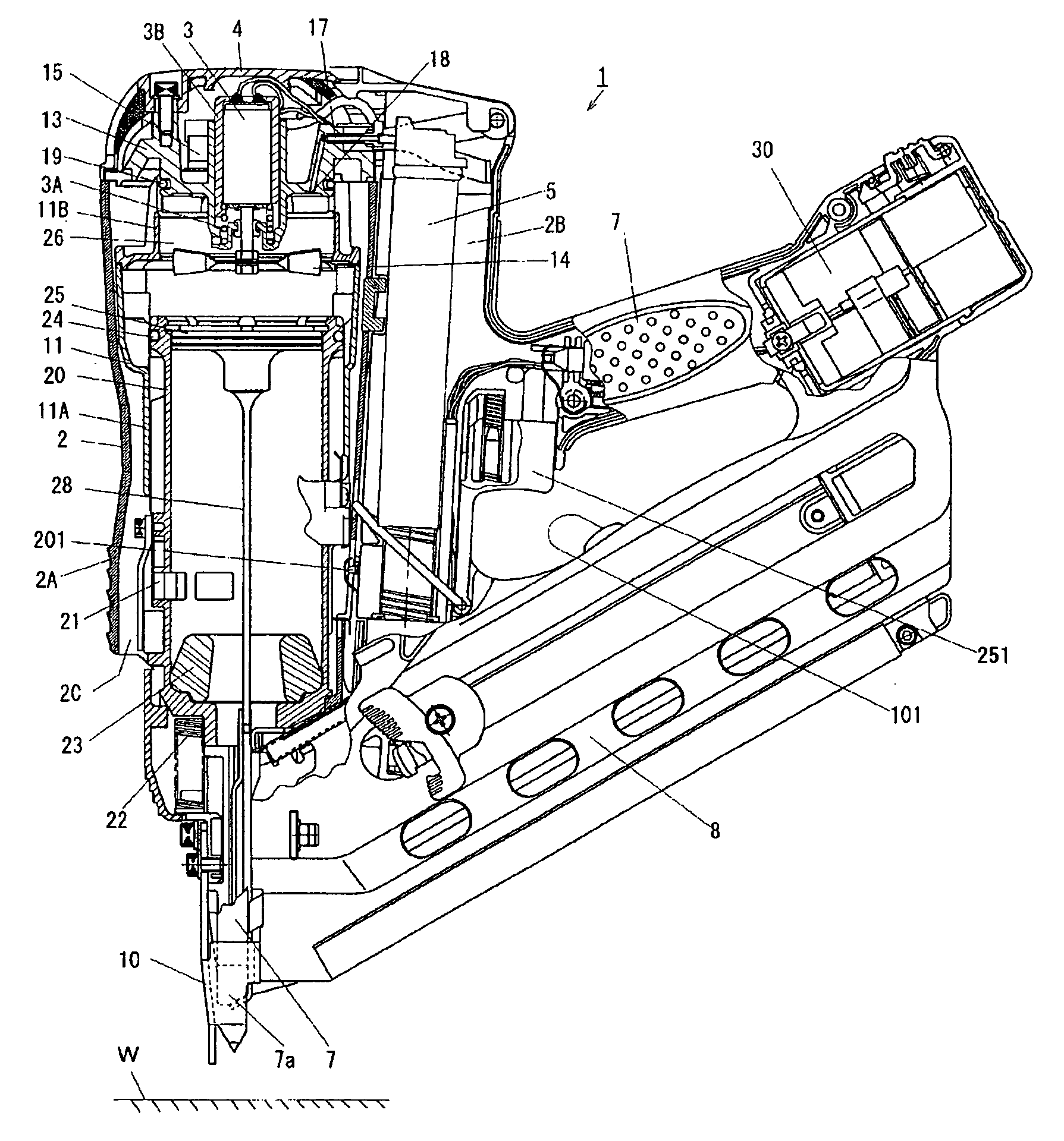
[0057]A combustion-powered, fastener-driving tool according to the invention will be described while referring to FIGS. 4 through 9 where like components and parts as appeared in FIG. 1 are designated by like reference numerals and duplicate description thereof is omitted. In FIG. 4, reference numerals 251 and 201 designate a trigger switch and a push switch that function similar to the trigger switch 6 and the head switch 16 of FIGS. 1 and 2, respectively.

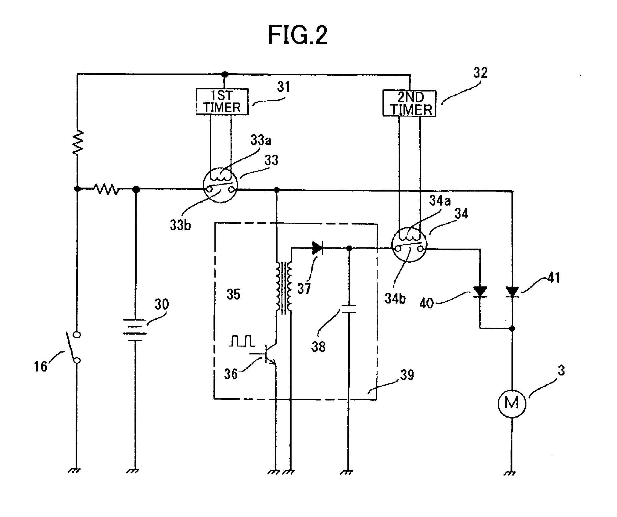
[0058]In the vicinity of the trigger switch 251 and above the magazine 8, a main switch 101 is disposed. When the main switch 101 is closed or turned ON, the voltage across the battery 30 is applied to a control circuit 51 shown in FIGS. 6A and 6B and the tool 1 is placed in a usable condition. On the other hand, when the main switch 101 is opened or turned OFF, the control circuit 51 is not powered. Therefore, by turning the main switch 101 OFF, it is possible to block dissipation of energy of the battery 30 when the tool 1 is n...


PUM

PropertyMeasurementUnit
nominal voltageaaaaaaaaaa
voltageaaaaaaaaaa
voltageaaaaaaaaaa

Abstract

A combustion-powered driving tool for driving nails or other fasteners in which the starting characteristics of a motor in the tool are improved by varying the amount of voltage applied to the motor when starting the motor and during normal operations so that the motor is driven to reach the rotational speed required in normal operations quickly. Therefore, the combustion-powered driving tool does not require the use of an expensive low-inertia motor, but can use a relatively inexpensive core-type motor or the like with inferior starting characteristics, while improving the work efficiency and user-friendliness of the combustion-powered driving tool.

Description

BACKGROUND OF THE INVENTION[0001]1. Field of the Invention[0002]The present invention relates to a combustion-powered tool, and more particularly to a combustion-powered, fastener-driving tool for driving nails or other fasteners. In such a fastener-driving tool, liquefied gas contained in a gas tank is injected into a combustion chamber, where the liquefied gas is mixed with air and ignited. The power generated from this combustion drives a piston, which in turn drives the nail or other fastener into a workpiece.[0003]2. Description of the Related Art[0004]Combustion-powered tools of the type described above are disclosed in U.S. Pat. Nos. 4,483,474; 4,403,722; 4,522,162 and 5,592,580. A typical combustion-powered tool primarily includes a housing, handle, trigger switch, head cap, combustion chamber frame, push lever, cylinder, piston, driver blade, motor, fan, gas tank, spark plug, exhaust check valve, magazine, and tail cover. The head cap seals one end of the housing. The handl...

Claims


Application Information

Patent Timeline
Patent Type & Authority Patents(United States)
IPC IPC(8): B25C1/08B25C1/00
CPCB25C1/08
Inventor FUJISAWA, HARUHISAOHMORI, YASUKINISHIKAWA, TOMOMASA
Owner KOKI HLDG CO LTD
Why Eureka
Try Eureka