Projector with light source having variable brightness based on detected temperature information

a technology of temperature information and projector, which is applied in the direction of picture reproducers, picture reproducers using projection devices, instruments, etc., can solve the problems of reducing the size and noise of the projector, and the voltage limitation of the fan, so as to achieve low noise, small size, and reliable operation

Inactive Publication Date: 2005-05-03
SHARP NEC DISPLAY SOLUTIONS LTD
View PDF17 Cites 98 Cited by
  • Summary
  • Abstract
  • Description
  • Claims
  • Application Information

AI Technical Summary

Benefits of technology

[0008]It is therefore an object of the present invention to provide a cooling structure for a projector, which is arranged to make the projector small in size, low in noise, and reliable in operation, and a method of controlling such a cooling structure.
[0011]With the above arrangement, since the temperature detecting means directly detects the temperature of a component of the optical engine or an ambient air temperature, a margin up to the allowable temperature of the electronic device in the optical engine can be known. If the margin is small, then the light source electric energy changing means reduces the electric energy supplied to the light source, and if the margin is large, then the light source electric energy changing means increases the electric energy supplied to the light source. This control process makes it possible to realize a small-size, low-noise projector because it is not necessary to employ a high-speed or large-diameter cooling fan in view of the temperature of the environment where the projector is installed.

Problems solved by technology

However, because of growing demands for low-noise environments, it is general practice to employ a variable-speed fan for cooling projectors, and lower the rotational speed of the variable-speed fan when the ambient temperature around the projector drops below an allowable temperature for various components of the projector.
However, there is a certain limitation on the voltages that can be applied to fans.
However, such a fan of higher cooling capability presents a major obstacle to efforts to reduce the size and noise of the projector.

Method used


Image

  • Projector with light source having variable brightness based on detected temperature information
  • Projector with light source having variable brightness based on detected temperature information
  • Projector with light source having variable brightness based on detected temperature information

Examples


1st embodiment

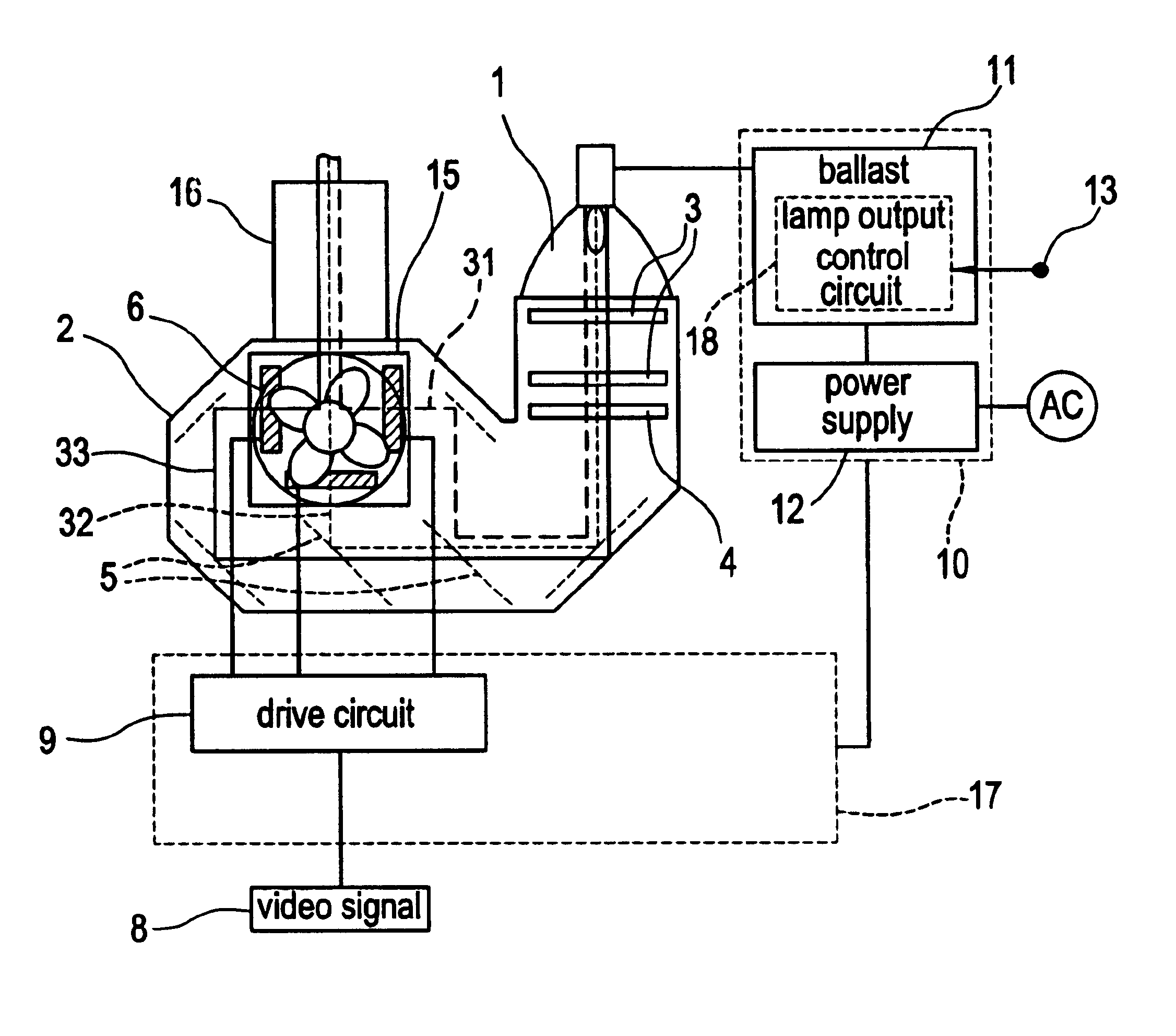
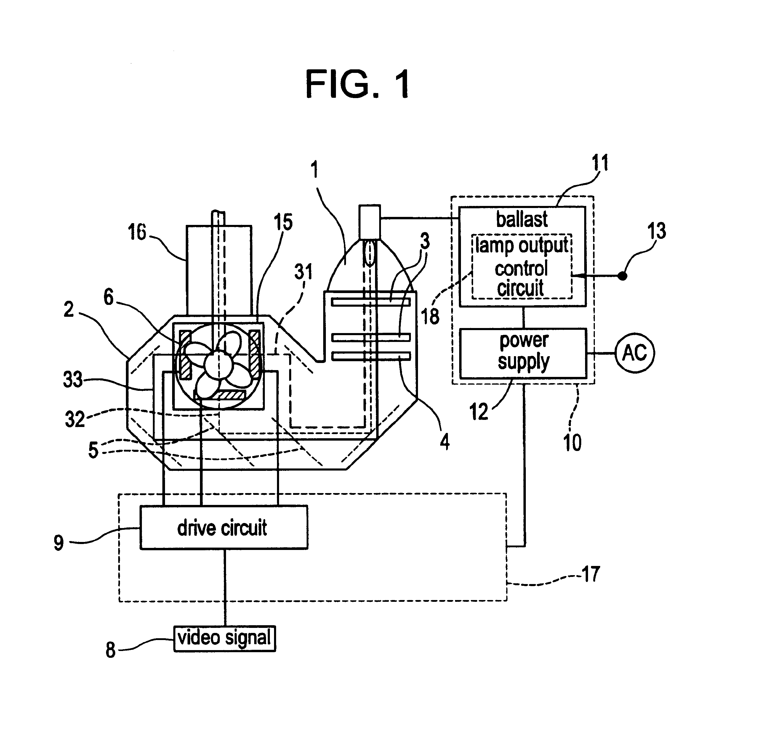
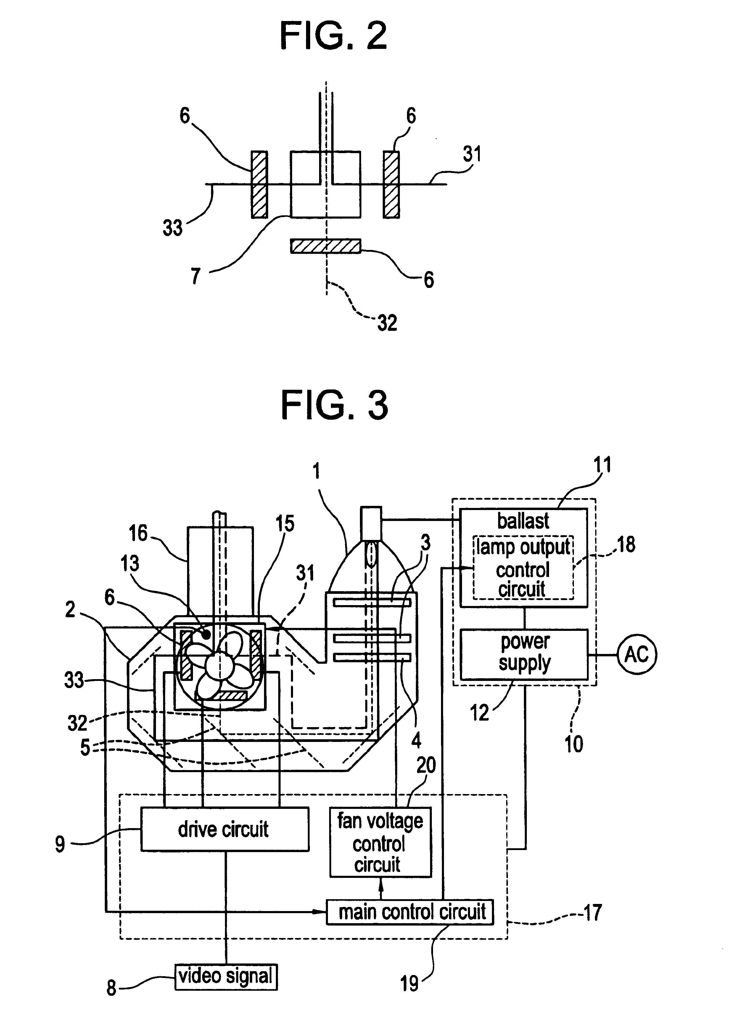
[0025]FIG. 1 shows, partly in block form, a three-panel liquid crystal projector according to a first embodiment of the present invention, and FIG. 2 shows, at an enlarged scale, a liquid crystal panel assembly of the three-panel liquid crystal projector sown in FIG. 1.

[0026]As shown in FIG. 1, the three-panel liquid crystal projector according to the first embodiment comprises ultrahigh-pressure mercury lamp 1 serving as a light source for emitting light based on supplied electric energy, optical engine 2, projection lens 16, electric circuit 17, power supply 10 for supplying electric energy to electric circuit 17 and ultrahigh-pressure mercury lamp 1, cooling fan 15 for cooling components of optical engine 2, and temperature sensor 13 serving as a temperature detecting means for detecting the temperature of ambient air.

[0027]Optical engine 2 generates an image with an optical means and liquid crystal panels 6 based on the light emitted from ultrahigh-pressure mercury lamp 1. The o...

2nd embodiment

[0038]FIG. 3 shows, partly in block form, a three-panel liquid crystal projector according to a second embodiment of the present invention. In the first embodiment described above, the principles of the present invention are applied to a conventional projector having a cooling fan whose rotational speed is constant. According to the second embodiment, a function to change the electric energy supplied to ultrahigh-pressure mercury lamp 1 is added to another conventional projector having a cooling fan whose rotational speed is changed depending on the temperature of the environment where the projector is installed. As shown in FIG. 3, details of the optical paths extending from ultrahigh-pressure mercury lamp 1 to projection lens 16 and details of power supply 10 of the three-panel liquid crystal projector according to the second embodiment are identical to those of the three-panel liquid crystal projector according to the first embodiment. Therefore, only those parts of the three-pan...

3rd embodiment

[0048]An additional function that is applicable to the liquid crystal projectors according to the first and second embodiments will be described below. FIG. 6 shows a characteristic portion of a liquid crystal projector according to a second embodiment of the present invention. In FIG. 6, image 22 is projected onto screen 22 by projection lens 16 of the liquid crystal projectors shown in FIGS. 1 and 3.

[0049]In the third embodiment, image 22 projected onto screen 22 includes comment (sentence) 24 stating brightness changes and display bar 23 for displaying patterns that visually indicate brightness changes to the observer of image 22. One example of comment 24 is “BRIGHTNESS IS BEING LOWERED”, indicating to the observer that the projector is automatically adjusting its brightness.

[0050]FIG. 7 shows in detail a pattern of brightness changes displayed by display bar 23, which successively shift from bright level 25 to dark level 26. FIG. 8 shows in detail a pattern of brightness change...


PUM


Abstract

A projector changes stepwise electric energy supplied to a light source based on temperature information which is detected by a temperature sensor. The temperature sensor detects the temperature of components of an optical engine or an ambient air temperature. A lamp output control circuit changes stepwise the electric energy supplied to the light source based on the temperature information detected by the temperature sensor.

Description

BACKGROUND OF THE INVENTION[0001]1. Field of the Invention[0002]The present invention relates to a cooling structure for a projector and a method of controlling such a cooling structure.[0003]2. Description of the Related Art[0004]Heretofore, projectors have been cooled by a fan which is operated under a fixed drive voltage of 12 V, for example. However, because of growing demands for low-noise environments, it is general practice to employ a variable-speed fan for cooling projectors, and lower the rotational speed of the variable-speed fan when the ambient temperature around the projector drops below an allowable temperature for various components of the projector. The variable-speed fan is associated with a sensor for detecting the ambient temperature, and the rotational speed of the variable-speed fan is changed depending on the detected ambient temperature.[0005]According to another speed control scheme, rather than the variable-speed fan changing the rotational speed thereof, t...

Claims


Application Information

Patent Timeline
Patent Type & Authority Patents(United States)
IPC IPC(8): G03B21/16H04N9/31H05K7/20G03B21/00
CPCG03B21/16H04N9/3117H05K7/20209H04N9/3155H04N9/3197H04N9/3144
Inventor OKADA, TAKAYUKIMATSUDAIRA, ATSUSHI
Owner SHARP NEC DISPLAY SOLUTIONS LTD
Why Eureka
Try Eureka