Shielded reflective light-emitting diode
a light-emitting diode and shielding technology, applied in the direction of identification means, light source combinations, instruments, etc., can solve the problems of reducing and affecting the brightness of the display. , to achieve the effect of reducing the unevenness of the display
- Summary
- Abstract
- Description
- Claims
- Application Information
AI Technical Summary
Benefits of technology
Problems solved by technology
Method used
Image

Examples
embodiment 1
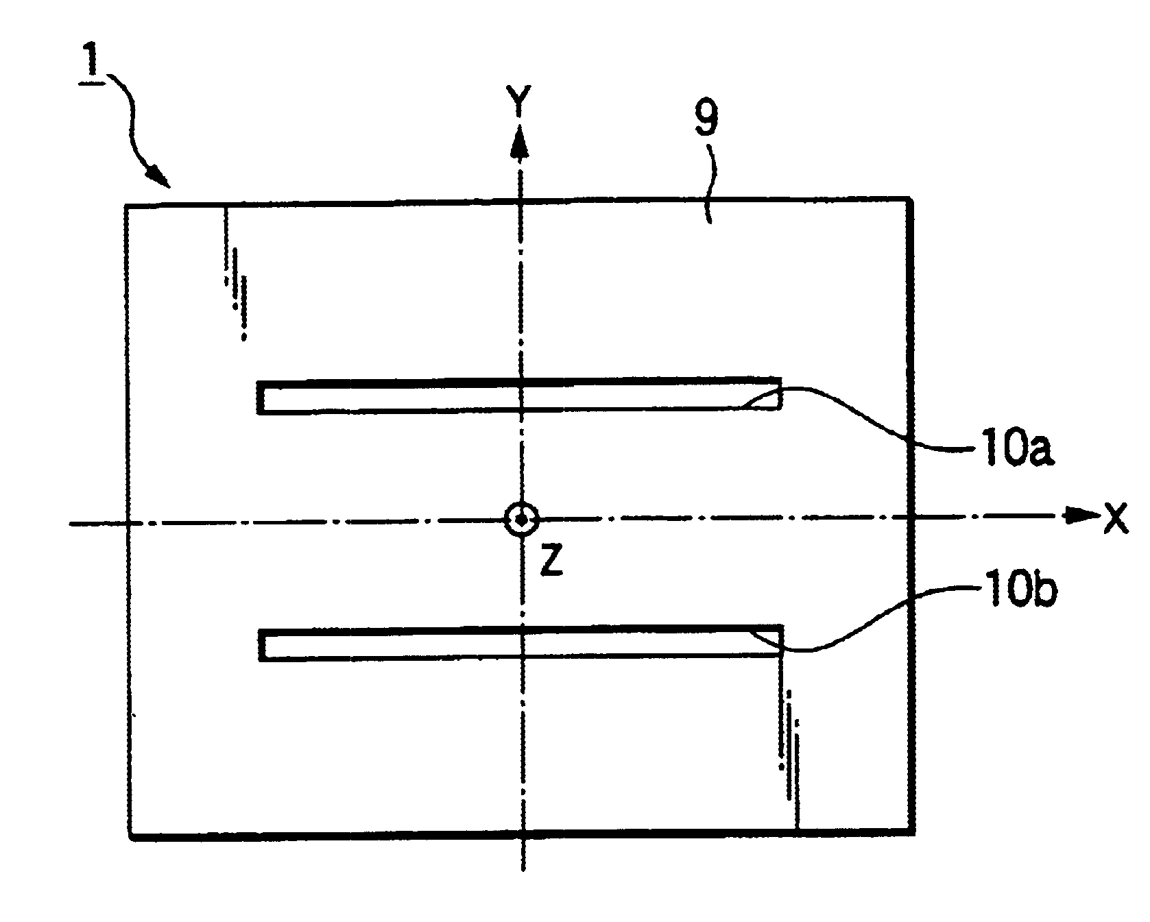
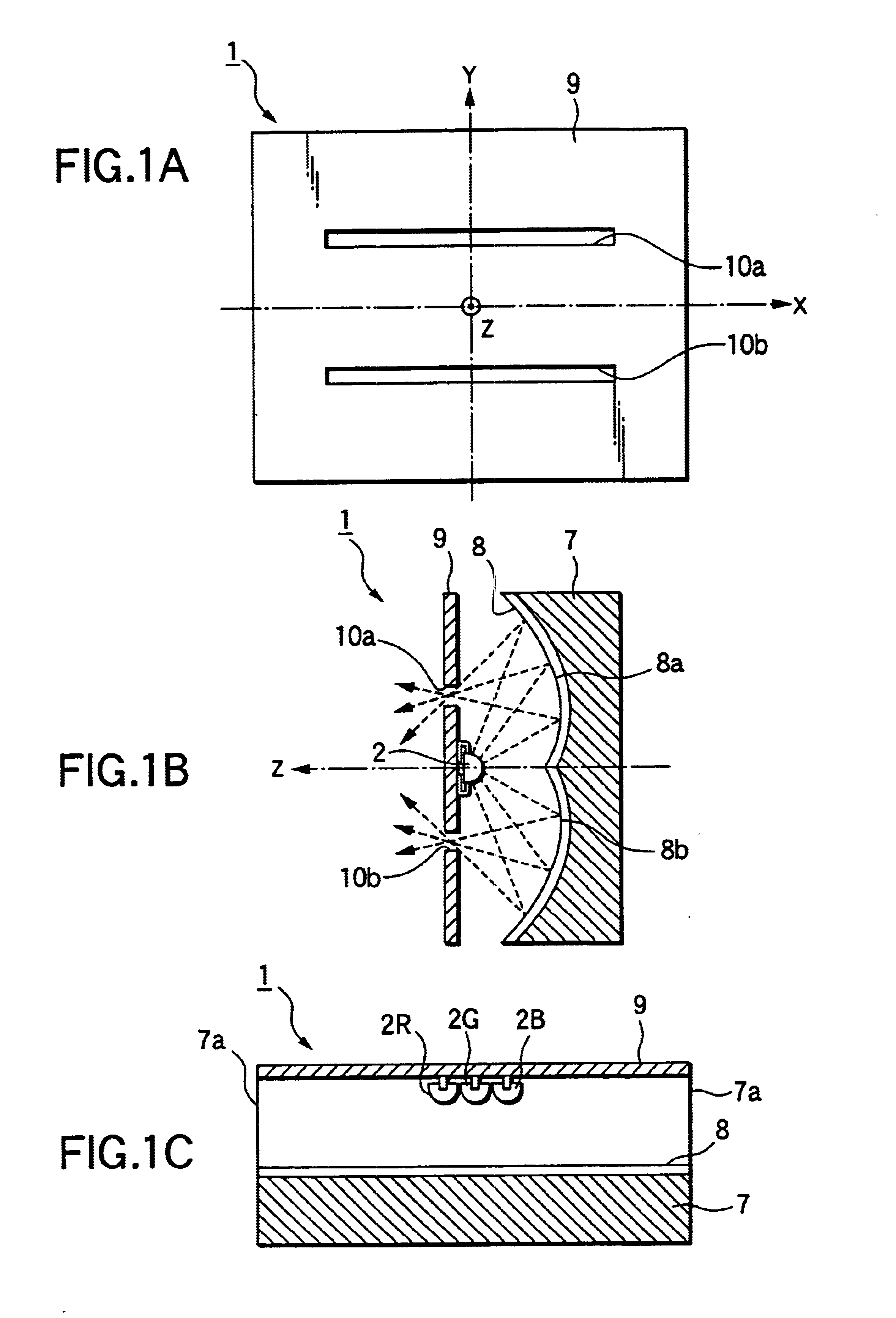
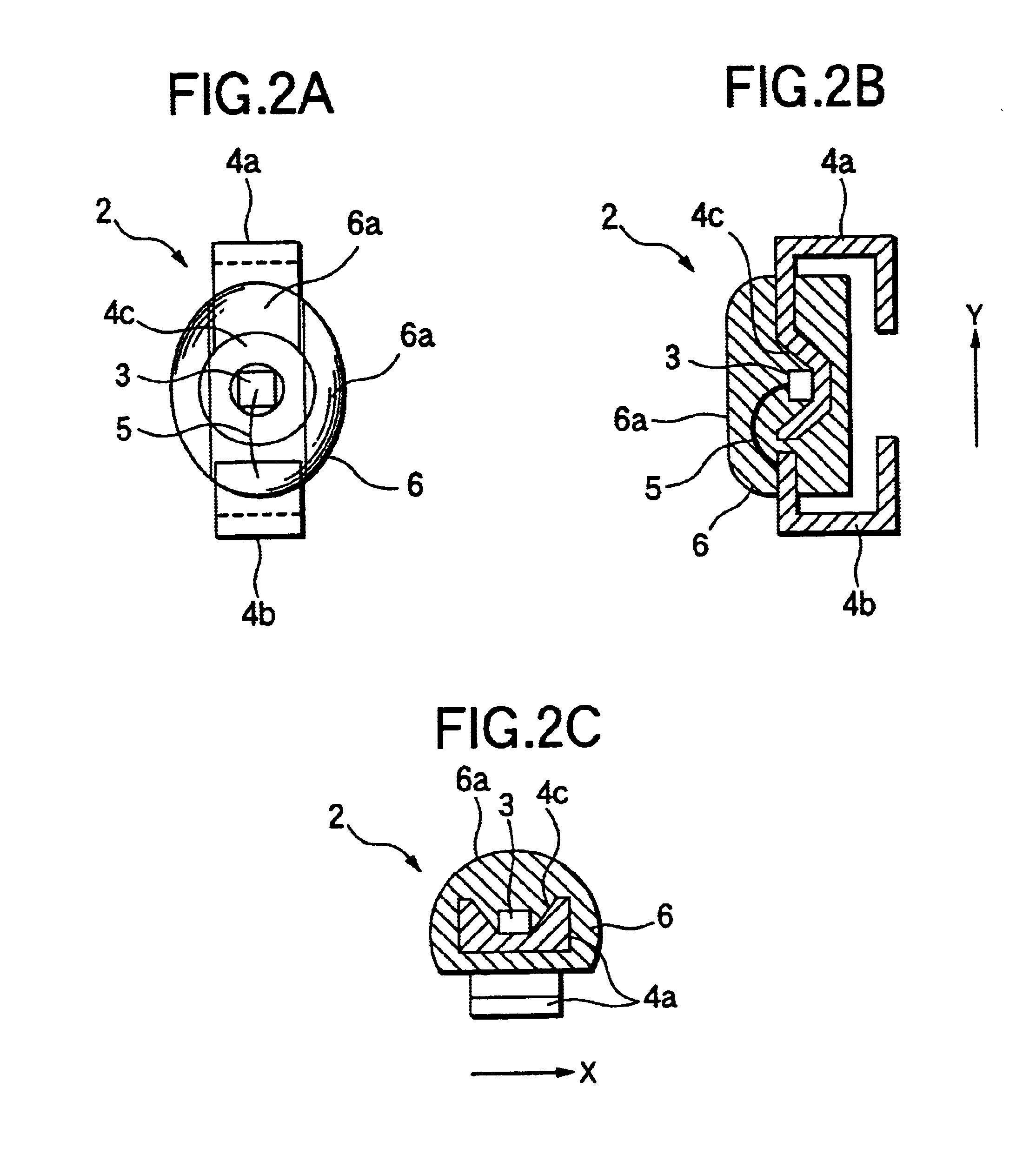
[0074]Referring first to FIGS. 1A to 1C and FIGS. 2A to 2C, Embodiment 1 of the invention will be described. FIG. 1A is a plan view showing the configuration of a shielded reflective light-emitting diode according to Embodiment 1 of the invention. FIG. 1B is a longitudinal sectional view taken along the Y direction in FIG. 1A. FIG. 1C is a longitudinal sectional view taken along the X direction in FIG. 1A. FIG. 2A is a plan view showing the configuration of a light source used in the shielded reflective light-emitting diode according to Embodiment 1 of the invention. FIG. 2B is a longitudinal sectional view taken along the Y direction. FIG. 2C is a longitudinal sectional view taken along the X direction.
[0075]As shown in FIG. 1A, in the shielded reflective LED 1 according to Embodiment 1, two slit-like optical opening portions 10a and 10b extended in the X direction are formed in a light-shielding member 9 which serves also as a mount substrate. LED light is radiated out through the...
embodiment 2
[0084]Referring to FIGS. 3A to 3C, Embodiment 2 of the invention will be described below. FIG. 3A is a plan view showing the configuration of a shielded reflective light-emitting diode according to Embodiment 2 of the invention. FIG. 3B is a longitudinal sectional view taken along the Y direction in FIG. 3A. FIG. 3C is a longitudinal sectional view taken along the X direction in FIG. 3A.
[0085]As shown in FIG. 3A, in the shielded reflective LED 1 according to Embodiment 2, four slit-like optical opening portions 20a, 20b, 20c and 20d extended in the X direction are formed in a light-shielding member 19 which serves also as a mount substrate. LED light is radiated out through these optical opening portions 20a, 20b, 20c and 20d.
[0086]As shown in FIG. 3B, a light source 2 having a light-emitting element is mounted on a rear surface of the light-shielding member 19 and between the optical opening portions 20b and 20c. The configuration of the light source 2 is the same as that in Embod...
embodiment 3
[0103]Referring to FIGS. 4 through 7, a shielded reflective device (shielded reflective light-emitting diode) and a light source according to Embodiment 3 of the invention will be first described. FIG. 4 is a front view showing the periphery of an optical opening portion in the shielded reflective device according to Embodiment 3 of the invention. FIG. 4 is a longitudinal sectional view showing the shielded reflective device according to Embodiment 3 of the invention. FIG. 5 is a plan view showing the overall configuration of the light source according to Embodiment 3 of the invention. FIG. 7 is a longitudinal sectional view showing the overall configuration of the light source according to Embodiment 1 of the invention.
[0104]As shown in FIG. 4, a shielded reflective LED 1 which is the shielded reflective device according to Embodiment 3 of the invention has an optical opening portion 102 which is substantially circularly shaped and very narrow. Even in the case where the optical op...
PUM
 Abstract
Description
Claims
Application Information
 - R&D
- Intellectual Property
- Life Sciences
- Materials
- Tech Scout
- Unparalleled Data Quality
- Higher Quality Content
- 60% Fewer Hallucinations
Browse by: Latest US Patents, China's latest patents, Technical Efficacy Thesaurus, Application Domain, Technology Topic, Popular Technical Reports.
© 2025 PatSnap. All rights reserved.Legal|Privacy policy|Modern Slavery Act Transparency Statement|Sitemap|About US| Contact US: help@patsnap.com