Tribologically improved design for variable stator vanes

a technology of variable stator valves and stator valves, which is applied in the direction of machines/engines, mechanical equipment, liquid fuel engines, etc., to achieve the effects of reducing cost, facilitating durability, and reducing air leakag

Inactive Publication Date: 2005-05-03
GENERAL ELECTRIC CO
View PDF43 Cites 32 Cited by
  • Summary
  • Abstract
  • Description
  • Claims
  • Application Information

AI Technical Summary

Benefits of technology

[0010]The present invention presents improvements to the bushing and washer forming the bearing assembly at the outer radial end of a stator vane, the outer bearing assembly, and the bearing assembly at the inner radial end of the stator vane, the inner bearing assembly that facilitate durability, effectiveness and reduced cost.
[0011]Both the inner and outer bearing assemblies are designed to rotate relative to the vane shaft and the respective mating shroud or case to even out the wear around the circumference of the bushing. However, the bushing is designed so that if the relative wear rate between the bushing material and the vane or the shroud / case is high, the bushing will not rotate relative to that material. When a rotating bushing is used, a flange on the bushing is designed to be positioned on the inside of the case, so that a pressure differential across the case applies a force to the vane to move it outwardly against the flange and the flange against the case, thereby minimizing air leakage.
[0012]The vane is designed to have an axial bearing face adjacent to a vane stem at each end, such that the axial bearing face bears against the bushing flange or a washer to minimize wear and friction. The axial bearing face has a larger diameter for harder, less wearing materials than the adjacent bushing flange and a smaller diameter than the adjacent bushing flange for a softer, more wearing surface to minimize edge effects and “digging-in” abrasion. This configuration can also be applied to a lever arm bearing face which rides against a bushing flange / washer located between it and the casing to reduce wear as the lever arm rotates. The sliding contact forces between the lever arm, vane stems and their respective shroud or case are fully carried by the bushings and washers for the design life of the assembly.
[0014]Advantages of the present invention are that the bearing assembly and associated, vane and case / shroud design extends system life, increases system temperature capability beyond known values, reduces air leakage and minimizes repair costs when the engine is refurbished. The extended system life of the bearing assembly allowing the variable stator vane to operate over the entire design life of the assembly translates to improved engine performance and lower operating cost of the engine.

Problems solved by technology

However, the bushing is designed so that if the relative wear rate between the bushing material and the vane or the shroud / case is high, the bushing will not rotate relative to that material.

Method used


Image

  • Tribologically improved design for variable stator vanes
  • Tribologically improved design for variable stator vanes
  • Tribologically improved design for variable stator vanes

Examples


Embodiment Construction

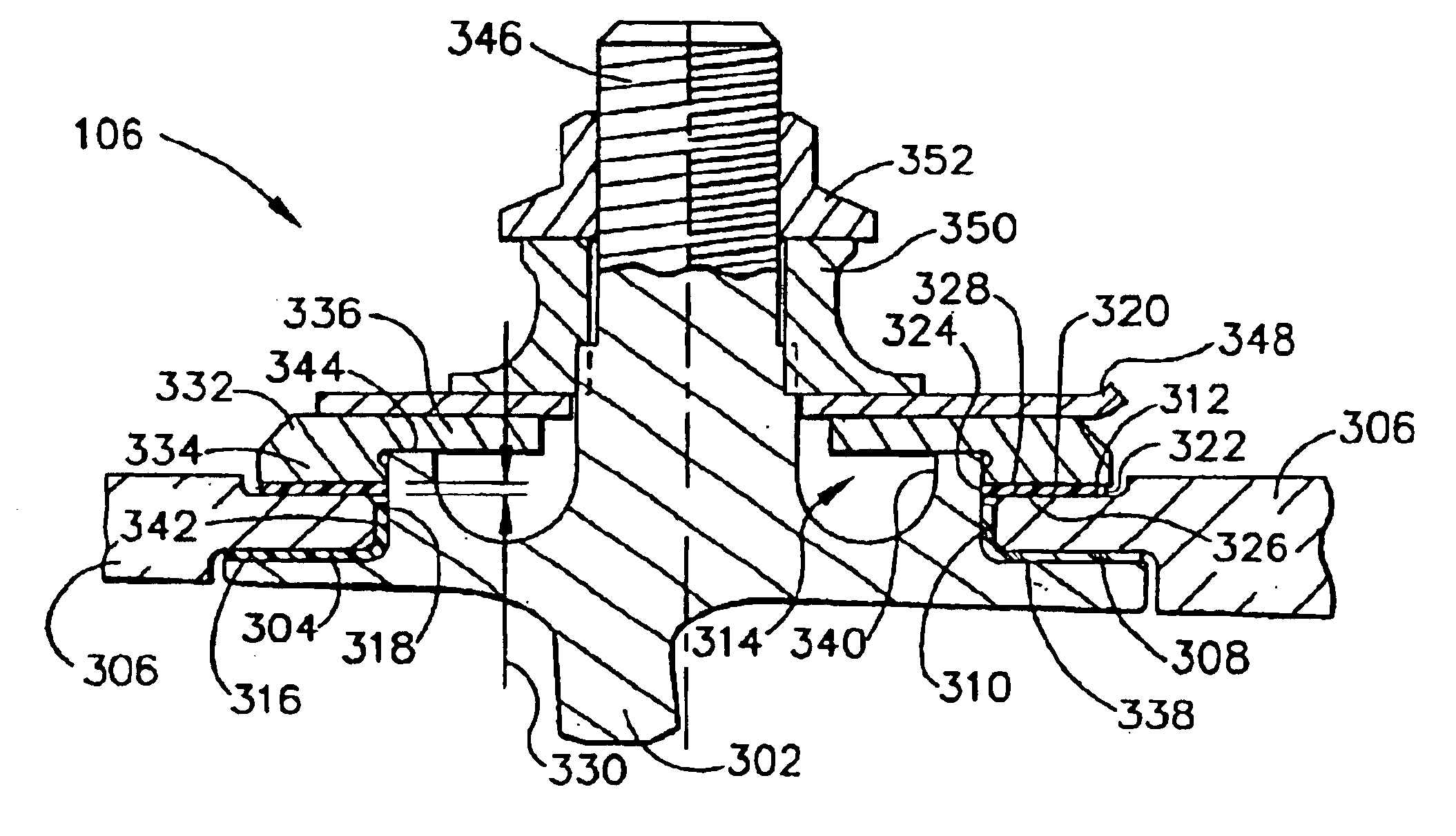
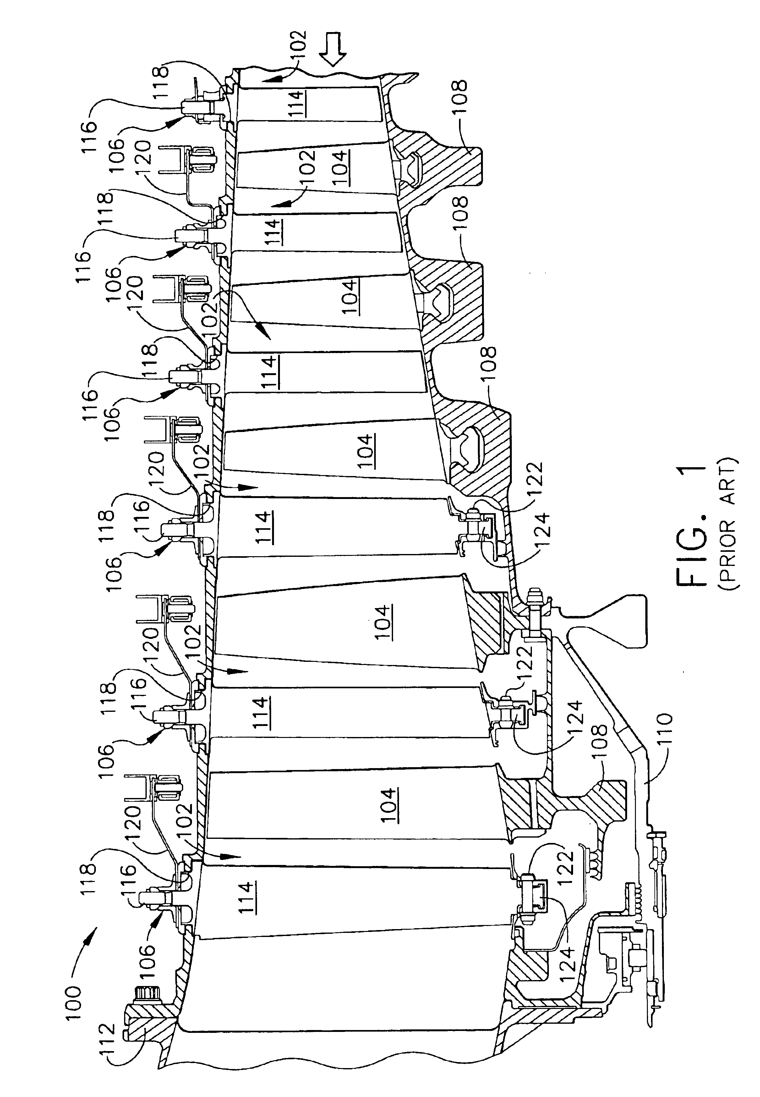
[0020]FIG. 1 is a schematic view of a section of a portion of a typical compressor 100 for a turbine engine (not shown). Six variable stages are shown; however for large engines there typically are more stages, as many as thirteen or fourteen stages. The number of stages is not relevant as each stage operates in the same manner, the overall number of stages being an indication of the volume of air compressed and the degree of compression. A compressor 100 includes a plurality of stages 102, and each stage 102 includes a rotor disk 108 supporting a plurality of rotor blades 104 axially spaced from a set of radially oriented variable stator vane assemblies 106. Rotor disks 108 are assembled onto a rotor shaft 110. For simplicity, only a single spool is shown, however it will be understood by those skilled in the art that multiple spool designs are encompassed by this disclosure. Rotor shaft 110 is also connected at the aft end to a turbine (not shown). Rotor shaft 110 is surrounded by...


PUM

PropertyMeasurementUnit
thicknessaaaaaaaaaa
pressureaaaaaaaaaa
angleaaaaaaaaaa

Abstract

A bushing and washer forming a bearing assembly at the outer radial end of a stator vane, the outer bearing assembly, and the bearing assembly at the inner radial end of the stator vane, the inner bearing assembly, that facilitate durability, effectiveness and reduced cost. Both the inner and outer bearing assemblies are designed to rotate relative to the vane shaft and the respective mating shroud or case to even out the wear around the circumference of the bushing. When a rotating bushing is used, a flange on the bushing is designed to be positioned on the inside of the case, so that a pressure differential across the case applies a force to the vane to move it outwardly against the flange and the flange against the case, thereby minimizing air leakage.

Description

FIELD OF THE INVENTION[0001]This invention relates generally to fan and compressor components of gas turbine engines, and in particular, to bushings and washers used with variable stator vanes in the compressor section of the engine.BACKGROUND OF THE INVENTION[0002]In gas turbine engines, for example, aircraft engines, air is drawn into the front of the engine, compressed by a shaft-mounted rotary compressor, and mixed with fuel. The mixture is burned, and the hot combustion gases are passed through a turbine mounted on a shaft. The flow of hot gases turns the turbine, which turns the shaft and powers the compressor. The hot exhaust gases flow from the back of the engine, providing thrust that propels the aircraft forward.[0003]Gas turbine engines generally include a high pressure compressor for supplying combustion air to a combustor, and a turbine. The high pressure compressor, combustor, and turbine are collectively referred to as a core engine. Typically, gas turbine engines als...

Claims


Application Information

Patent Timeline
Patent Type & Authority Patents(United States)
IPC IPC(8): F01D17/16F01D17/00F04D29/40F04D29/04F04D29/56F04D29/057
CPCF01D17/162F04D29/057F04D29/563F05D2300/2118F05D2240/50F05D2300/2283Y02T50/672Y02T50/60F04D29/083
Inventor BRUCE, ROBERT W.
Owner GENERAL ELECTRIC CO
Why Eureka
Try Eureka