Coolant pump, mainly for automotive use

a technology for cooling pumps and automotive applications, applied in the direction of coolant flow control, liquid fuel engine components, refrigeration components, etc., can solve the problems of engine overheating and the difficulty for a designer to achieve the desired degree of linearity of control

Inactive Publication Date: 2005-05-03
FLOWORK SYST II
View PDF18 Cites 9 Cited by
  • Summary
  • Abstract
  • Description
  • Claims
  • Application Information

AI Technical Summary

Benefits of technology

[0015]It should be noted that, in an internal combustion engine, it is required that the coolant flow be maintained at all times during operation of the engine. The minimum flow demand is still a substantial flow. The engine would overheat in a few seconds if flow were actually to stop. Thus, it will be understood that the flow rate being controlled is just the upper fraction of the maximum flow rate—an area of flow in which it is notoriously difficult for a designer to achieve a desired degree of linearity of control. It is recognized that controlling just the upper fraction of the flow rate is not only easy with the variable pitch vanes, but, when the vanes are moved, the change in flow rate is not too far from being more or less linearly proportional to the movement of the vane. This means that simple automotive wax-type thermostats can be used directly, since they too have a more or less linear temperature / movement characteristic.

Problems solved by technology

The engine would overheat in a few seconds if flow were actually to stop.
Thus, it will be understood that the flow rate being controlled is just the upper fraction of the maximum flow rate—an area of flow in which it is notoriously difficult for a designer to achieve a desired degree of linearity of control.

Method used


Image

  • Coolant pump, mainly for automotive use
  • Coolant pump, mainly for automotive use
  • Coolant pump, mainly for automotive use

Examples


Embodiment Construction

[0019]By way of further explanation of the invention, exemplary embodiments of the invention will now be described with reference to the accompanying drawings. In which:

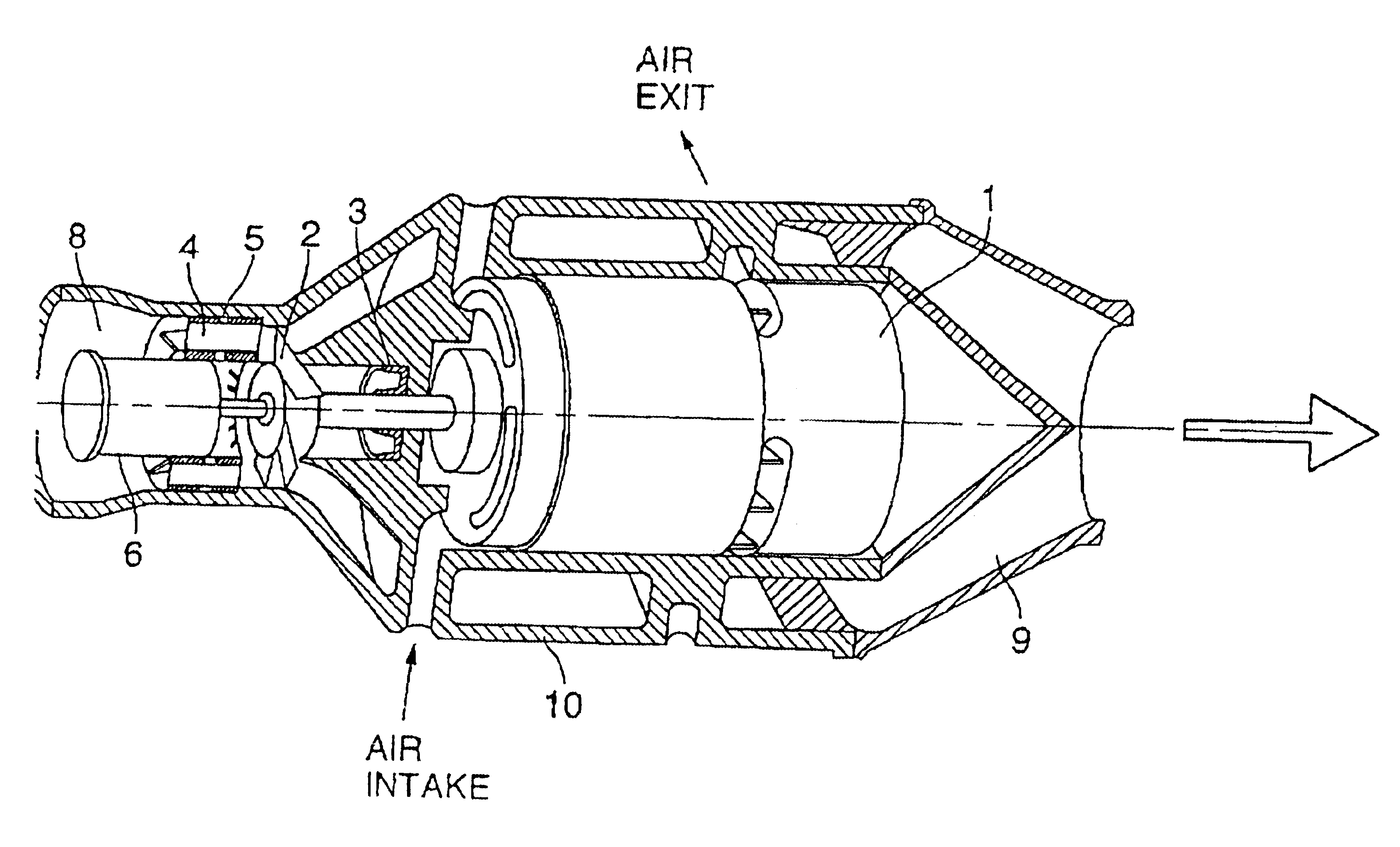
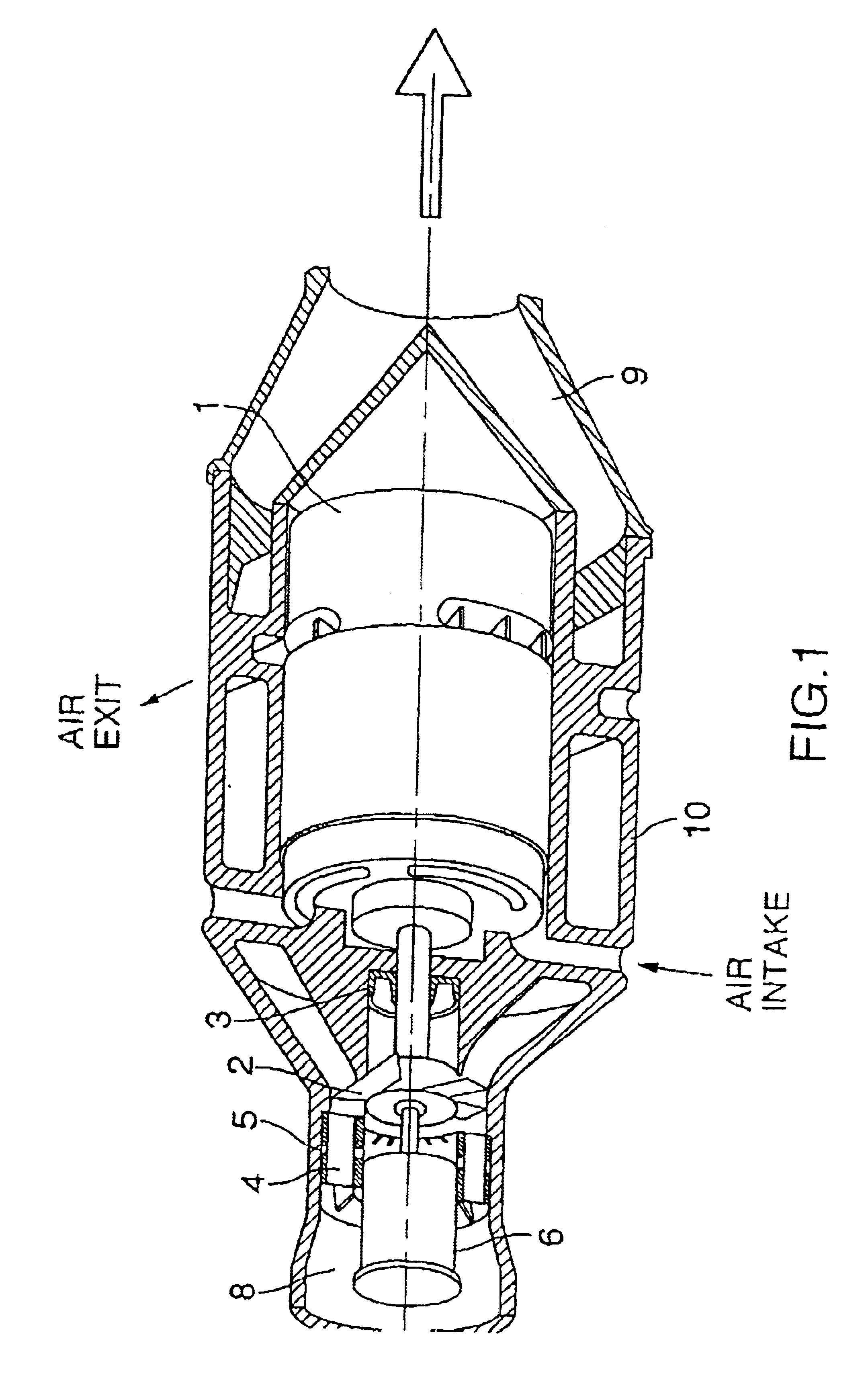
[0020]FIG. 1 is a pictorial cross-section of a water pump which embodies the invention;

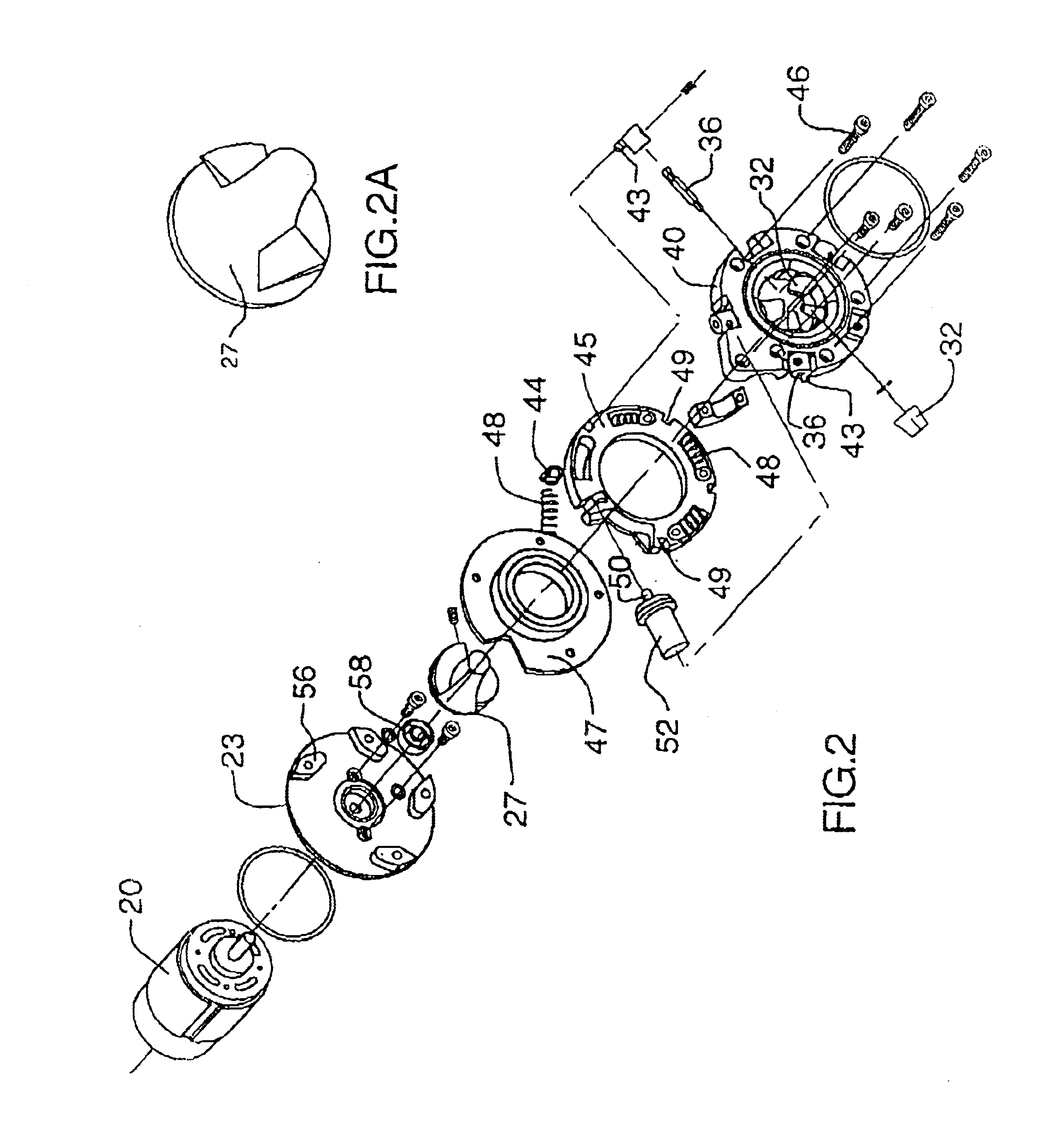
[0021]FIG. 2 is a pictorial exploded view of the components of a water pump for an automotive engine, which embodies the invention;

[0022]FIG. 2a is a close-up of an impeller of the pump;

[0023]FIG. 3 is a pictorial view in close up of the assembled components of the pump of FIG. 2;

[0024]FIG. 4 is a diagrammatic cross-sectioned side view of some of the components of the pump of FIG. 2;

[0025]FIG. 5 is an end elevation of some of the components of the pump of FIG. 2;

[0026]FIG. 6 is cross-section of another water pump which embodies the invention;

[0027]FIG. 7 is a cross-section on line A—A of FIG. 6;

[0028]FIG. 8 is a pictorial view of some of the components of the pump of FIG. 6;

[0029]FIG. 9 is a cross-section of another water pump whic...


PUM


Abstract

An impeller pump with thermostatically adjustable guide vanes is suitable for use as an automotive coolant pump. The pump is driven by a constant speed electric motor, and flow variation is controlled by varying the orientation of the vanes. Orientation of the vanes is effected by a wax-type thermostat, which senses coolant temperature: flow is increased when the coolant is hot, and decreased as the coolant cools. The variable guide vanes are mounted for pivoting about radial axes, and are located just upstream from the pump impeller.

Description

[0001]This is a Continuation-in-Part of patent application Ser. No. 09 / 848,224, filed 4 May 2001, now granted and issued as U.S. Pat. No. 6,499,963, derived from patent application Ser. No. 09 / 125,861, filed 23 Aug. 1998, now granted as U.S. Pat. No. 6,309,193, issued 30 Oct. 2001, derived from PCT / CA-97 / 00123, filed 25 Feb. 1997, claiming priority date of 26 Feb. 1996 from GB-96 / 4042.3.[0002]This invention relates to coolant pumps for automotive internal-combustion engines. The invention is aimed at providing a coolant pump which delivers flow characteristics in accordance with engine demand.BACKGROUND TO THE INVENTION[0003]Pumps for internal-combustion engine cooling systems have traditionally been belt-driven, at a fixed ratio, directly from the engine.[0004]The coolant flow rate and pressure head required to effectively control the engine temperature are not, however, optimal when driven proportionally to the engine's rotational speed. The coolant system has to cope with the ful...

Claims


Application Information

Patent Timeline
Patent Type & Authority Patents(United States)
IPC IPC(8): F01P5/10F01P5/00F01P7/16F01P7/14F04D15/00F04D29/40F04D29/46F04D29/56F01P5/12
CPCF01P5/10F01P7/16F04D29/566F04D15/0027F04D15/0038F04D29/466F01P7/161F01P2005/125F01P2007/146F01P2070/00F01P2060/08F04D29/22F04D29/46F04D29/56
Inventor REPPLE, WALTER OTTOFULTON, JOHN ROBERT LEWIS
Owner FLOWORK SYST II
Why Eureka
Try Eureka